Radio paging receiver and message erasing method

a message and receiver technology, applied in the field of radio paging receivers, can solve the problems of troublesome utilization and ineffective utilization of storage areas, and achieve the effect of effectively utilizing message storage areas

Inactive Publication Date: 2006-07-18
PANASONIC CORP
View PDF17 Cites 20 Cited by
  • Summary
  • Abstract
  • Description
  • Claims
  • Application Information

AI Technical Summary

Benefits of technology

[0011]The present invention has been made to overcome the above problem, and it is an object of the present invention to provide a radio paging receiver which is capable of releasing the user from the complicatedness to erase message and also utilizing effectively a message storage area by not storing the message therein or by erasing the message therefrom automatically.

Problems solved by technology

As a result, the radio paging receiver has such a problem that its utilization has become troublesome because of the frequent user's operation of erasing the message data, and thus the storage area has not been able to be utilized effectively.

Method used


Image

  • Radio paging receiver and message erasing method
  • Radio paging receiver and message erasing method
  • Radio paging receiver and message erasing method

Examples


first embodiment

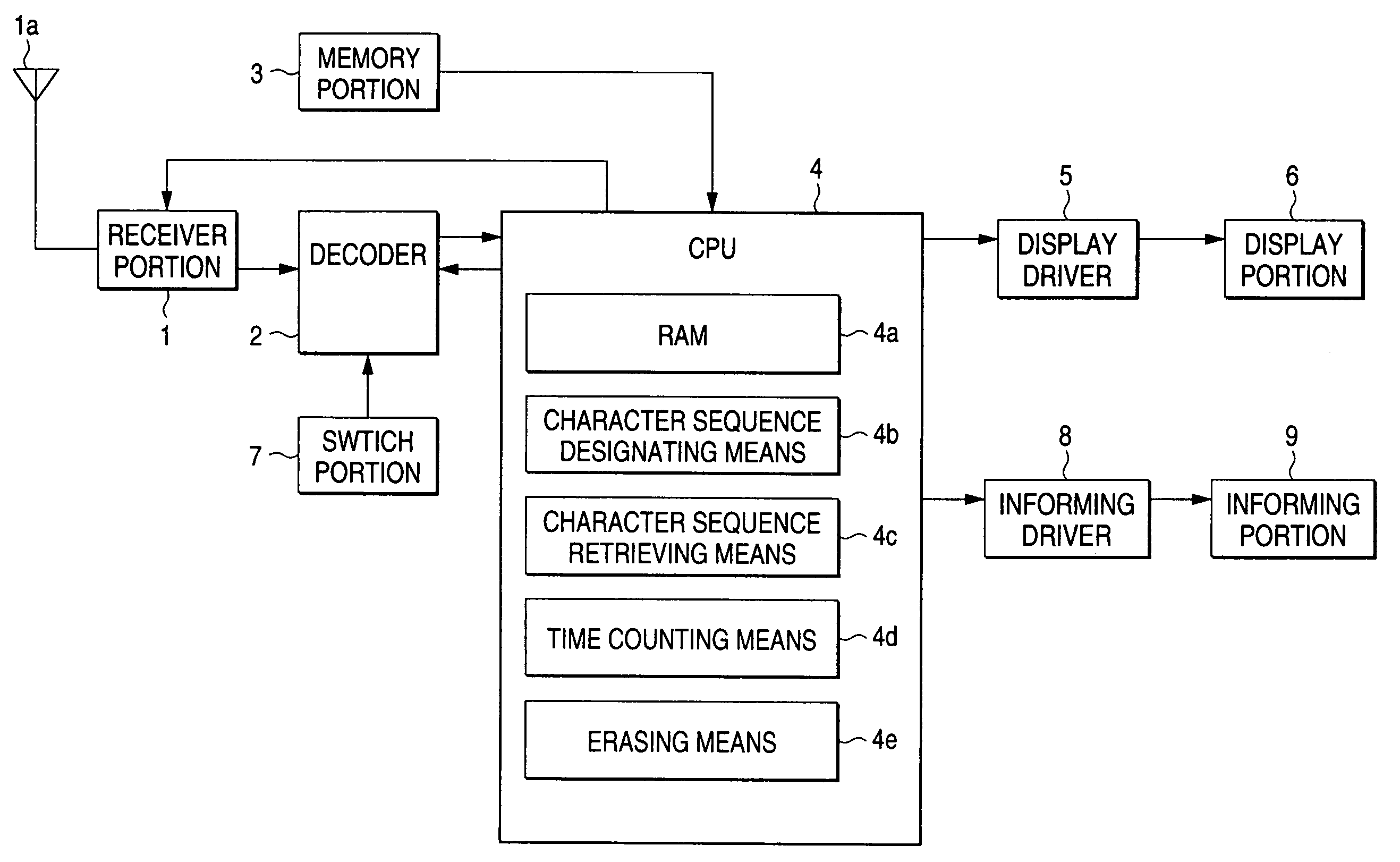
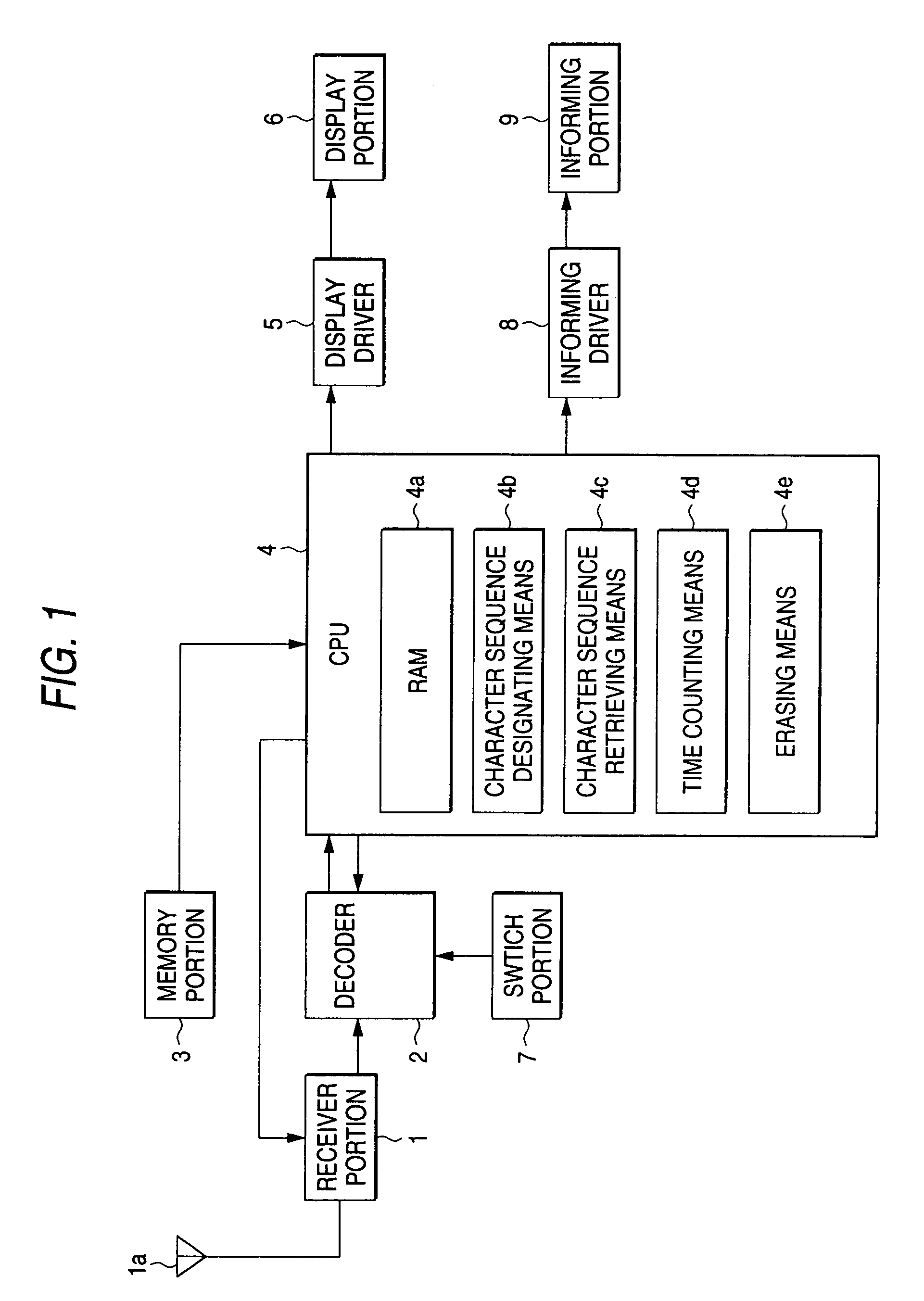
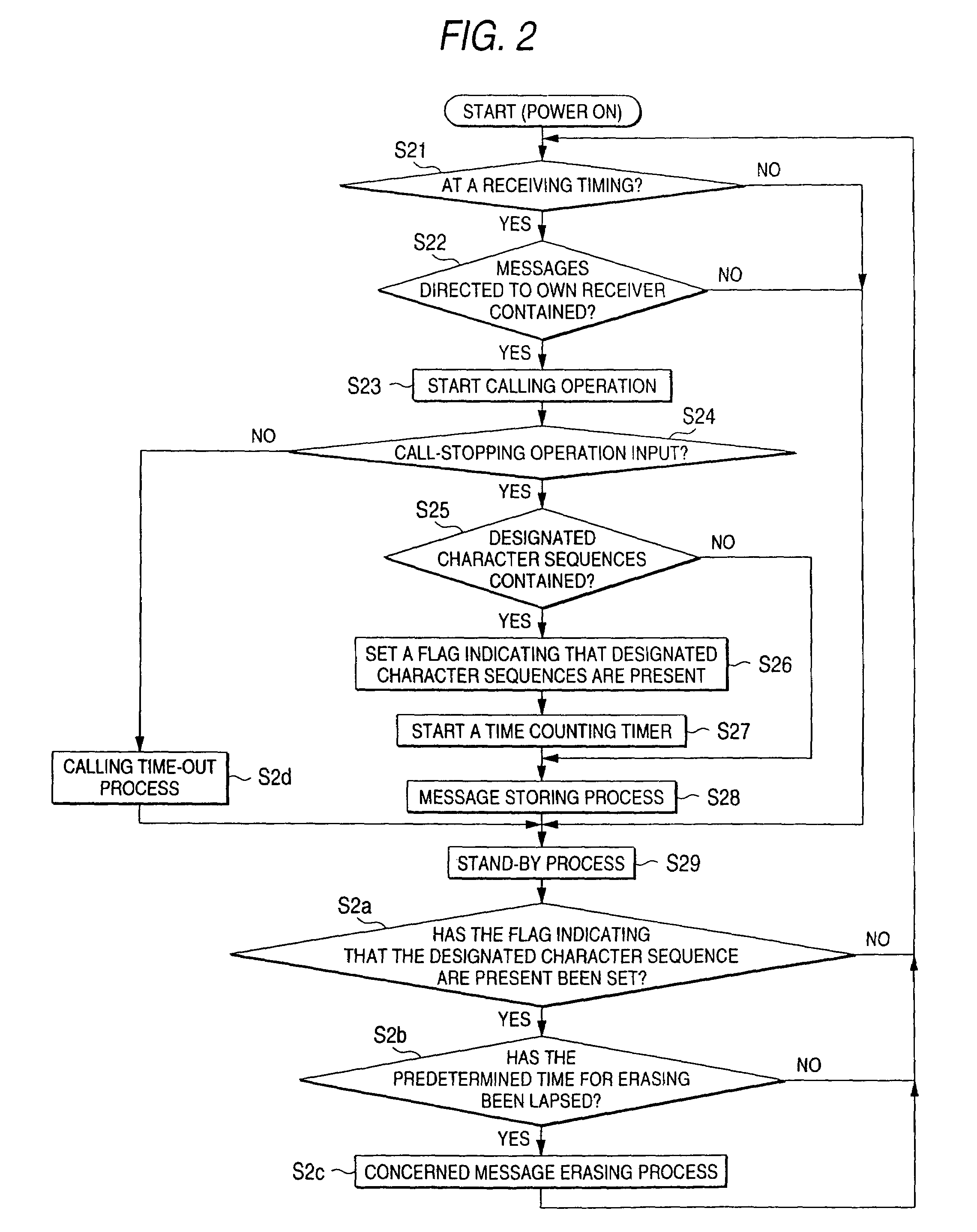
[0045]A first embodiment of the present invention corresponds to a radio paging receiver which can designate any character sequences in stored messages, and then erase the concerned messages automatically after a predetermined time has been lapsed from the time when the messages containing the character sequences are stored.

[0046]FIG. 1 is a block diagram showing a circuit configuration of the radio paging receiver according to the first embodiment of the present invention. In FIG. 1, a receiver portion 1 is a circuit which receives a radio signal transmitted from a base station (not shown) of a radio paging system, and then demodulates the radio signal into a digital signal. A decoder 2 is a circuit which applies a bit synchronization process and an error correction process to the received signal which has been converted into the digital signal, and then collates an address in the received signal with own address loaded in a memory portion 3. The memory portion 3 is a memory unit w...

second embodiment

[0055]A second embodiment of the present invention corresponds to a radio paging receiver which can erase automatically the message with designated addresses after a predetermined time has been lapsed from the storing operation of the message.

[0056]FIG. 3 is a block diagram showing a circuit configuration of the radio paging receiver according to the second embodiment of the present invention. In FIG. 3, the same symbols as those in FIG. 1 are affixed to constituent elements corresponding to the constituent elements which have been explained with reference to FIG. 1, and their explanation will be omitted. A difference between the radio paging receiver according to the second embodiment and radio paging receiver according to the first embodiment resides in that an address associated storing means 4f and an address setting means 4g are provided to the CPU 4.

[0057]In FIG. 3, the address associated storing means 4f is a means which enables to store the messages while discriminating each...

third embodiment

[0062]A third embodiment of the present invention corresponds to a radio paging receiver which can erase automatically the messages belonging to the designated hierarchy after a predetermined time has been lapsed from the storing operation.

[0063]FIG. 5 is a block diagram showing a circuit configuration of the radio paging receiver according to the third embodiment of the present invention. In FIG. 5, the same symbols as those in FIG. 1 are affixed to constituent elements corresponding to the constituent elements which have been explained with reference to FIG. 1, and their explanation will be omitted. A difference between the radio paging receiver according to the third embodiment and radio paging receiver according to the first embodiment resides in that a hierarchy associated storing means 4h and a hierarchy setting means 4i are provided to the CPU 4.

[0064]In FIG. 5, the hierarchy associated storing means 4h which enables to store the messages which are identified and transmitted ...


PUM


Abstract

Message data are picked up by using a decoder 2 from received signals received by a receiver portion 1 of a radio paging receiver, and stored in a RAM 4a of a CPU 4. An informing portion 9 informs a user of the message. The user designates any character sequences in the message stored in the RAM 4a by a character sequence designating unit 4b. A character sequence retrieving unit 4c retrieves whether or not designated character sequences are contained in stored messages. When the messages containing the designated character sequences are detected, a time counting unit 4d monitors whether or not a predetermined time has been lapsed after storage of concerned messages. An erasing unit 4e erases unnecessary messages stored in the RAM 4a from the RAM 4a after the predetermined time has been lapsed. Accordingly, the messages which are transmitted periodically and repeatedly to the radio paging receiver can be erased collectively and automatically and thus complicatedness in erasing the messages can be eliminated and also operability can be enhanced.

Description

BACKGROUND OF THE INVENTION[0001]1. Field of the Invention[0002]The present invention relates to a radio paging receiver and, more particularly, a radio paging receiver for displaying / calling a message corresponding to message data in a radio signal which is transmitted from a base station of a radio paging system.[0003]2. Description of the Prior Art[0004]FIG. 17 is a block diagram showing a circuit configuration of a radio paging receiver in the prior art. In FIG. 17, a receiver portion 21 is a circuit which receives a radio signal transmitted from a base station of a radio paging system via an antenna 21a, and then demodulates the radio signal into a digital signal. A decoder 22 is a circuit which applies a bit synchronization process and an error correction process to the received signal being converted into the digital signal, and then collates an address in the received signal with own address loaded in a memory portion 23. The memory portion 23 is a memory unit which has a me...

Claims


Application Information

Patent Timeline
Patent Type & Authority Patents(United States)
IPC IPC(8): G05B19/00G06F7/00G08B29/00H04B1/00H04Q9/00H04W88/02G08B5/22H04W84/02H04W88/18
CPCG08B5/227
Inventor ABE, YASUSHI
Owner PANASONIC CORP
Why Eureka
Try Eureka