
Method for determining the spatial location and position of a reflector rod in relation to a marked ground point

a technology of spatial location and position, applied in the direction of active open surveying means, instruments, surveying and navigation, etc., can solve the problems of inability to accurately determine the location of the ground point, inability to accurately determine the position of the reflector rod, and difficulty in achieving the effect of high reliability and accuracy

Active Publication Date: 2006-07-18
TRIMBLE JENA
View PDF5 Cites 12 Cited by
  • Summary
  • Abstract
  • Description
  • Claims
  • Application Information

AI Technical Summary

Benefits of technology

[0010]It is the primary object of the invention to create a method and an arrangement for determining the spatial location of a reflector rod above a support or ground point, wherein the disadvantages of the prior art are largely eliminated and all the rotations of the reflector rod in the coordinate system of the measuring station (base station) are covered in a simple way, with a high degree of reliability and accuracy, and are considered for the determination of measuring values during geodetic measurements.

Problems solved by technology

The height of the reflector above the ground point is measured manually in most cases today and, therefore, always constitutes a source of error.
The location of the ground point may be determined wrongly, inter alia, because of incorrect adjustment of the circular level on the reflector rod and improper rod placement on the ground point.
Furthermore, perpendicular placement of the rod requires a certain amount of time and is problematic whenever objects, such as shrubs and trees, obstruct the view between the tachymeter and the reflector prism or when points are hidden from view.
The fact that the measurements for the two reflectors are carried out separately is a disadvantage, however.
On the one hand, this procedure is time-consuming, while on the other a stable spatial location of the rod between two measurements cannot always be guaranteed.
Further, the two tilts of the rod are limited to the working range of the clinometer sensors, thus restricting the free spatial movement of the rod.
The third rotation, i.e., the rotation about the axis of the prism, cannot be determined in this way, which is a disadvantage of this method.
Another disadvantage is that the imaging optics used must image the bar code in a resolved manner, so that it can be measured in the image.
If there are greater distances between the imaging optics and the bar code of the staff, it is no longer possible to image the bar code in a resolved way.
The fact that additional clinometers are required constitutes a disadvantage.

Method used


Image

  • Method for determining the spatial location and position of a reflector rod in relation to a marked ground point
  • Method for determining the spatial location and position of a reflector rod in relation to a marked ground point

Examples


Embodiment Construction

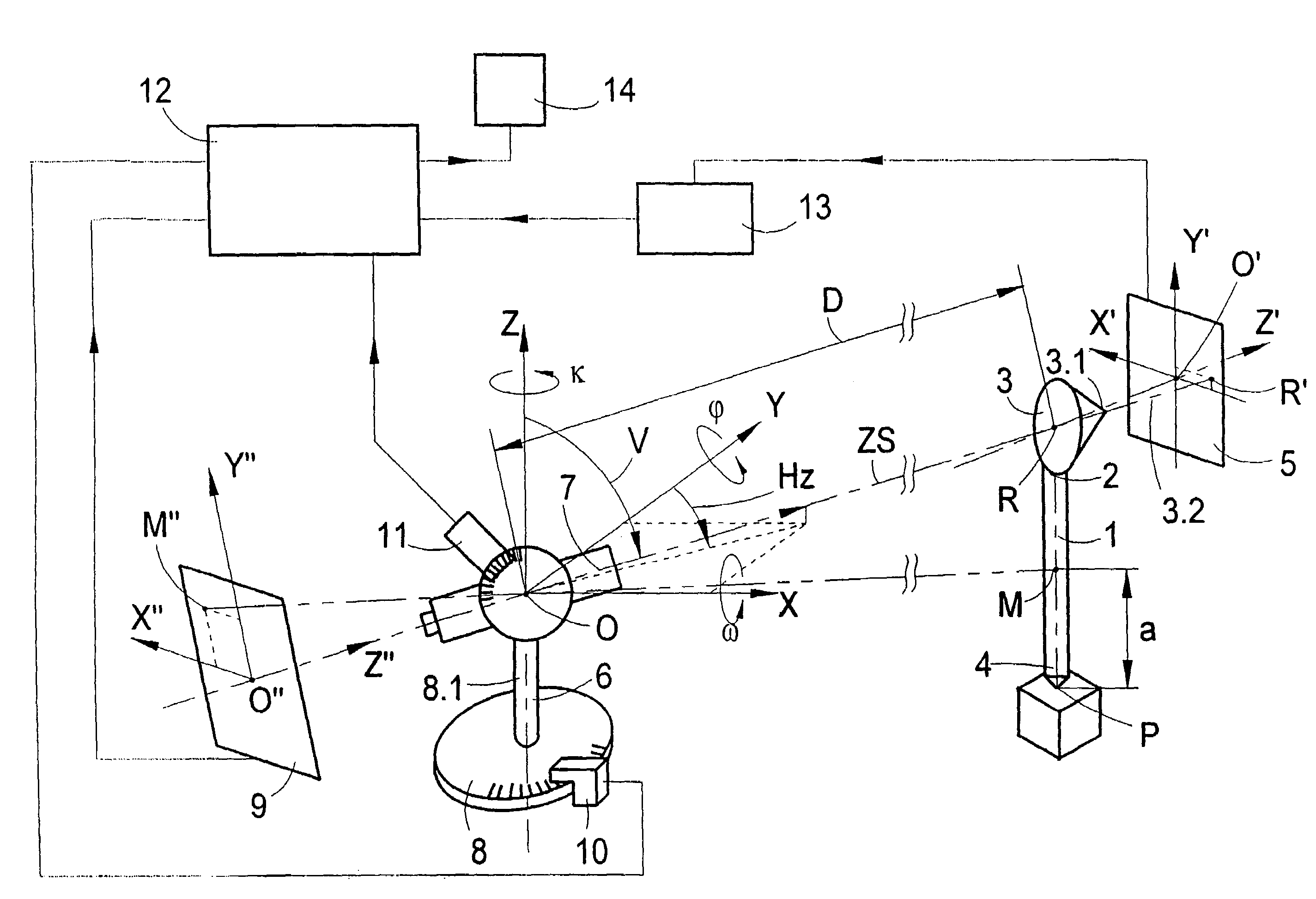
[0042]The arrangement, shown in FIG. 1, for determining the spatial location and position of a reflector rod put up on a ground or support point P at the target position comprises a reflector rod 1 to the upper end 2 of which a reflector 3 is fixed. The lower end 4 of the reflector rod 1 is placed on the support point P. The distance of the reflector 3 to the lower end 4 of the reflector rod 1 resting on the support point P is known for the geodetic measurements to be performed. However, it can also be changed to adapt it to different measurement conditions. The reflector 3 is a corner cube prism, as is common in measurements carried out in the field. Behind the reflector 3 or immediately next to it, a first position sensor 5 is arranged at a fixed, defined position and orientation in relation to the reflector 3 and provides first measurement data characterizing the location and position of the reflector 3 in relation to the sighting beam ZS. A first coordinate system with the coord...


PUM


Abstract

A method for determining the position of a reflector rod provided with a reflector, using a sighting beam emitted from a base station is disclosed. The reflector and a first position sensor define a first coordinate system. The direction of the sighting beam to the reflector is measured from the base station in a second coordinate system, using horizontal and vertical angles. A second position sensor arranged in the direction of the sighting axis of the base station determines the location and orientation of the reflector rod. Measurement data in the first coordinate system is generated to determine the spatial orientation of the reflector relative to the light beam. Imaging optics are used to image the reflector on the second position sensor. The position of the reflector in the second coordinate system and the distance from the base station to the reflector are determined.

Description

BACKGROUND OF THE INVENTION[0001]The invention is directed to a method for determining the spatial location and position of a reflector rod in relation to a marked ground point, notably when it comes to geodetic measurements in the field.[0002]In geodetic measurements, the location of a ground point, such as a boundary stone, is generally determined with the aid of a reflector that is attached to a reflector rod at a certain height above the ground point. The height of the reflector above the ground point is measured manually in most cases today and, therefore, always constitutes a source of error. In the field, this reflector rod is posed vertically on the ground point. By rotating the rod about the vertical rod axis, the reflector, e.g., a reflector prism or a corner cube prism, is aligned with a tachymeter or with another device employed to carry out the measurements. Following alignment, the actual measurement of horizontal and vertical angles and of distances can be performed. ...

Claims


Application Information

Patent Timeline
Patent Type & Authority Patents(United States)
IPC IPC(8): G01C1/00G01C15/00G01S5/16
CPCG01S5/163G01C15/002
Inventor VOGEL, MICHAEL
Owner TRIMBLE JENA
Learn More