Optical information medium, recording and reproduction apparatus, and recording and reproduction method

a technology of optical information medium and which is applied in the field of optical information medium, recording and reproduction apparatus, and recording and reproduction methods, can solve the problems of increasing the cost of optical discs as final products, insufficient memory capacity and recording speed of conventional optical discs to accumulate such high definition images, and difficulty in producing master discs with guide grooves which provide signals with low noise levels. , to achieve the effect of low cost, low cost, and high density

Inactive Publication Date: 2006-07-18
PANASONIC CORP
View PDF12 Cites 7 Cited by
  • Summary
  • Abstract
  • Description
  • Claims
  • Application Information

AI Technical Summary

Benefits of technology

[0032]Thus, the invention described herein makes possible the advantages of providing an optical information medium which can be produced at low cost and allows information to be recorded at a high density, and an optical information medium for reproduction only which allows a recording and reproduction apparatus for reproducing information from both a recordable opt

Problems solved by technology

Both the memory capacity and the recording speed of conventional optical discs are insufficient to accumulate such high definition images.
Therefore, it is difficult to form the groove to have a uniform depth in the ent

Method used


Image

  • Optical information medium, recording and reproduction apparatus, and recording and reproduction method
  • Optical information medium, recording and reproduction apparatus, and recording and reproduction method
  • Optical information medium, recording and reproduction apparatus, and recording and reproduction method

Examples


example 1

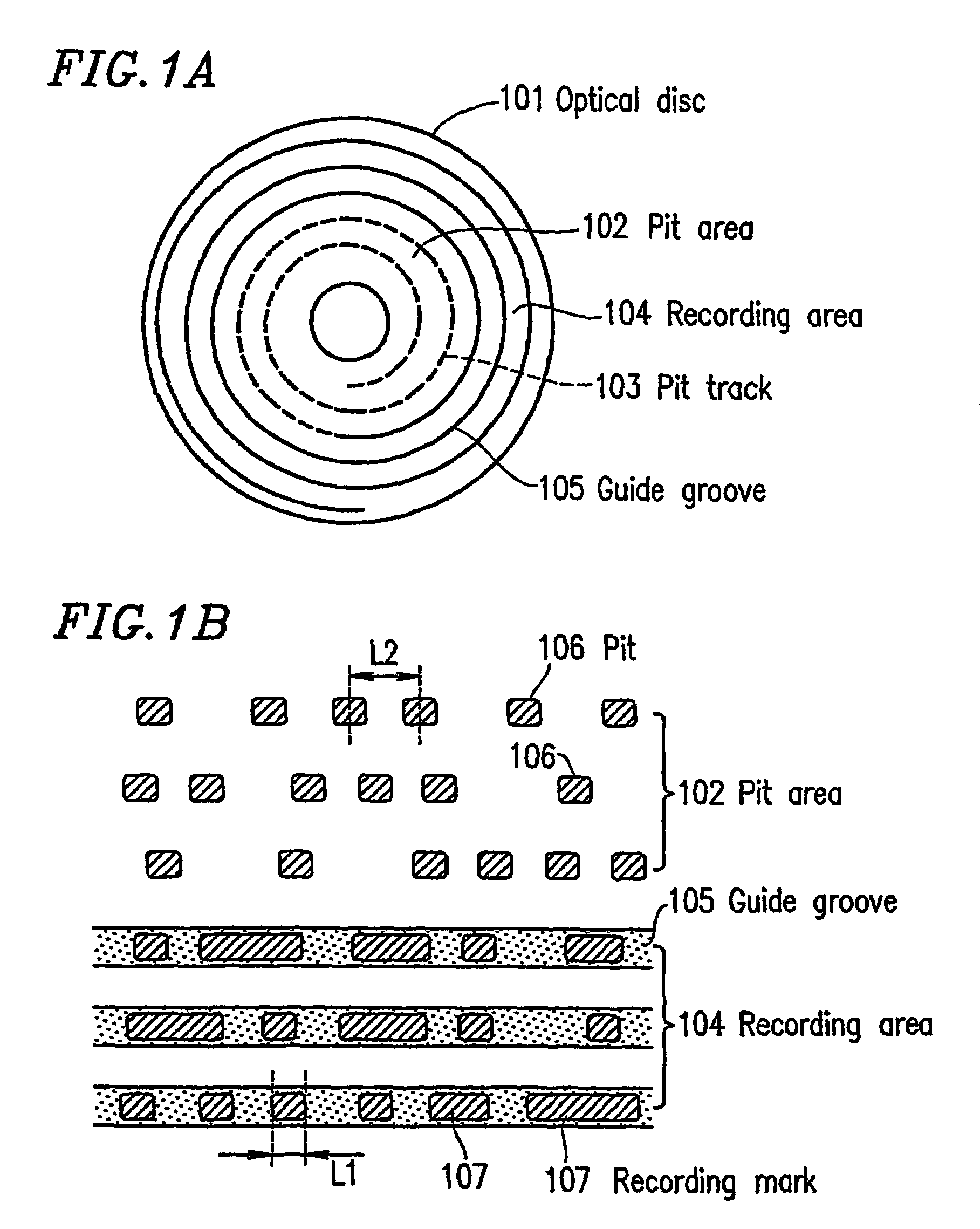
[0071]FIG. 1A shows a surface of a recordable optical disc 101 according to a first example of the present invention. The optical disc 101 includes a pit area 102 having a spiral pit track 103, and a recording area 104 having a spiral guide groove 105.

[0072]FIG. 1B is a partial enlarged view of the optical disc 101 shown in FIG. 1A. FIG. 1B shows the pit area 102, the recording area 104, and the vicinity thereof. The pit area 102 includes a plurality of concave and convex type pits 106 having an identical size in the spiral pit track 103. The pits 106 are PPM-recorded so that a length of each inter-pit 106 interval in the pit area 102 represents information. The recording area 104 has a plurality of recording marks 107 in the spiral guide groove 105. The recording marks 107 are PWM-recorded so that a length of each recording mark 107 in the recording area 104 represents information. Here, the minimum length of the recording mark 107 in th recording area 107 is L1, and the minimum le...

example 2

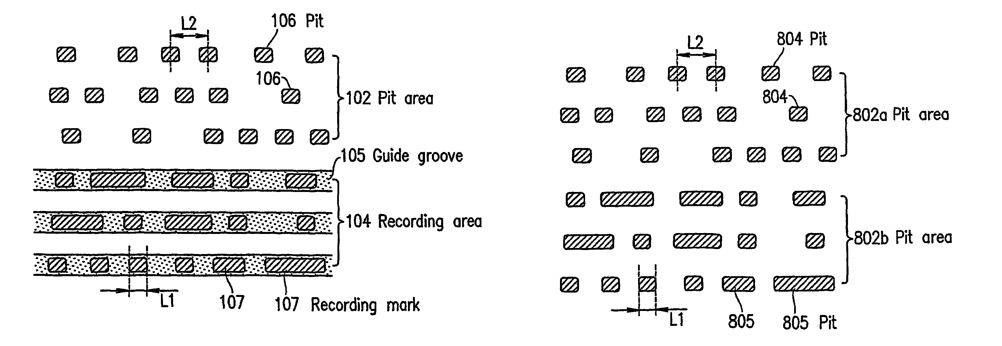
[0087]FIG. 8A shows a surface of a recordable optical disc 801 for reproduction only according to a second example of the present invention. The optical disc 801 includes pit areas 802a and 802b having a spiral pit track 803.

[0088]FIG. 8B is a partial enlarged view of the optical disc 801 shown in FIG. 8A. FIG. 8B shows the pit areas 802a and 802b and the vicinity thereof. The pit area 802 includes a plurality of concave and convex type pits 804 having a substantially identical size in the spiral pit track 803. The pits 804 are PPM-recorded so that a length of each inter-pit 804 interval in the pit area 802a represents information. The pit area 802b has a plurality of concave and convex type pits 805 in the pit track 803. The pits 805 are PWM-recorded so that a length of each pit 805 in the pit area 802b represents information. Here, the minimum length of the pits 805 in the pit area 802b is L1, and the minimum length of the inter-pit 804 intervals is L2. In the case of the optical ...

example 3

[0101]FIG. 12 is a block diagram illustrating a recording and reproduction apparatus 1200 for recording information on or reproducing information from a recordable optical disc 101 described in the first example.

[0102]The recording and reproduction apparatus 1200 includes a controller 1202, a head control circuit 1204, a second demodulation circuit 1205, a data read circuit 1206, a data accumulation circuit 1207, a modulation circuit 1209, a first demodulation circuit 1210, a data read circuit 1211, an optical head section 1212, and a data bus 1213. The optical head section 1212 includes an optical head 1203 and a laser control circuit 1208.

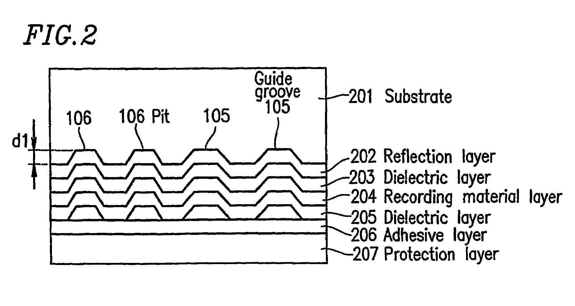
[0103]As described above, the depth of the pits in the pit area 102 of the optical disc 101 is substantially equal to the depth of the guide groove 105 (FIG. 1A). In the guide groove 105, information modulated by a first modulation system (for example, the 8–15 modulation system+the NRZI modulation system as shown in FIG. 3B) is recorded. The pit...


PUM


Abstract

A recordable optical information medium includes a recording area including a guide groove on which a recording material layer is provided for forming at least one recording mark which represents first information modulated by a first modulation system; and a pit area including at least one concave and convex type pit which represents second information modulated by a second modulation system. The guide groove and the at least one pit have substantially the same depth. The first modulation system and the second modulation system are different from each other.

Description

TECHNICAL FIELD[0001]The present invention relates to an optical information medium on which information is to be recorded or from which information is to be reproduced by a converged light beam directed thereto, and a recording and / or reproduction apparatus and a recording and / or reproduction method for recording information on or reproducing information from such an optical information medium.BACKGROUND ART[0002]Recently, DVDs (Digital Versatile Discs) have been widely used as optical information media (hereinafter, referred to as “optical discs”). As DVDs, there exist DVD-ROM discs for reproduction only, DVD-RW discs which are rewritable, and DVD-R discs which are of the write-once type.[0003]A DVD-RW disc has a memory capacity of 4.7 GB, with which at least 2 hours of NTSC moving pictures are recordable. The DVD-RW disc includes an inner lead-in area and a data area which is provided to outside the lead-in area in which information such as moving pictures or the like is to be re...

Claims


Application Information

Patent Timeline
IPC IPC(8): G11B7/00G11B7/005G11B7/007G11B7/013G11B7/24G11B7/24085G11B20/14
CPCG11B20/1403G11B7/24G11B7/24085G11B7/007G11B7/00G11B7/005
Inventor MORIYA, MITSUROISHIBASHI, HIROMICHI
Owner PANASONIC CORP
Why Eureka
Try Eureka