Performing multicast communication in computer networks by using overlay routing

Inactive Publication Date: 2006-07-18
GOOGLE LLC
View PDF12 Cites 110 Cited by
  • Summary
  • Abstract
  • Description
  • Claims
  • Application Information

AI Technical Summary

Benefits of technology

[0009]The present invention is to be embodied in a commercial product by FastForward Networks, called “MediaBridge.” Each MediaBridge is a process that is executed on a computer, or other processor or processing device, connected to a network. Multiple MediaBridges transfer data using an “overlay” network. In a preferred Internet embodiment, the overlay protocol uses “native” Internet protocols to route information, according to overlay routing tables, between otherwise disjoint and isolated multicast clouds. This allows the overlay distribution to

Problems solved by technology

However, a problem with such “streaming media” broadcasts is that they require very high data transfer rates across many servers, routers and local area networks that form the Internet.
Because of this, high-quality, scalable broadcasts, or “multicasts,” of streaming media information to massive numbers of end-users at once over the Internet have not been achieved to date.
While this approach works for today's demands, it wastes network bandwidth and cannot scale to very large audiences anticipated in the future.
Although some existing products (like NetShow and Cisco's IP/TV) support multicast, Internet Service Providers (ISPs) and enterprise network managers have been slow to adopt multicast because it is difficult to configure, manage, and debug.
For some companies, these deployment problems are crucial barriers because they view multicast as critical for their long-term viability and feel that failure to successfully integrate multicast c

Method used


Image

  • Performing multicast communication in computer networks by using overlay routing
  • Performing multicast communication in computer networks by using overlay routing
  • Performing multicast communication in computer networks by using overlay routing

Examples


Embodiment Construction

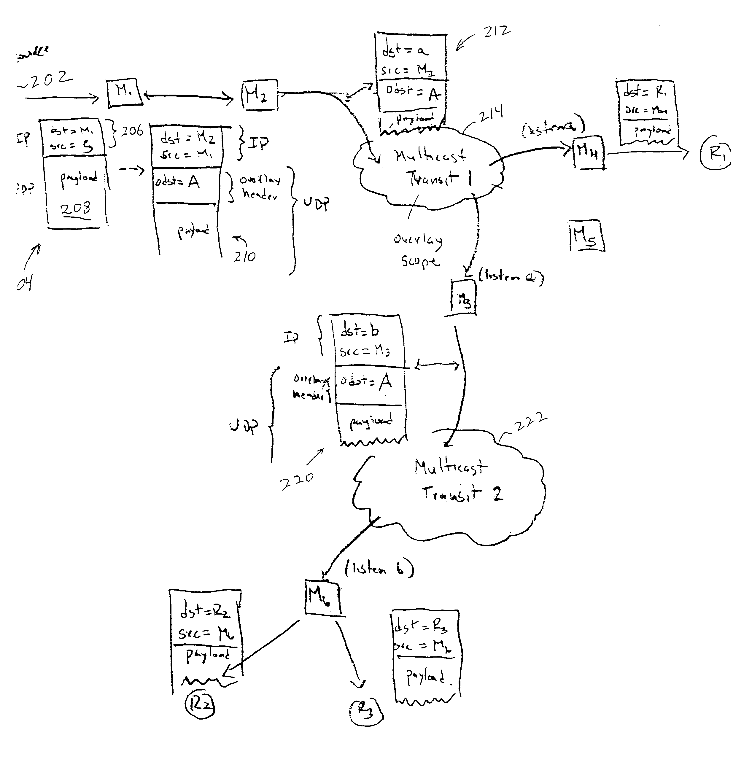
[0023]The present invention implements “overlay” multicasting. So-called because some of the routing processing by MediaBridge's uses a routing scheme that is independent of, in addition to, and at a higher level than the prior art “native” scheme. With the approach of the present invention, any of the current multicasting techniques, such as DVMRP, PIM, CBT, etc. are referred to as “native” multicasting,” or “native protocols.”

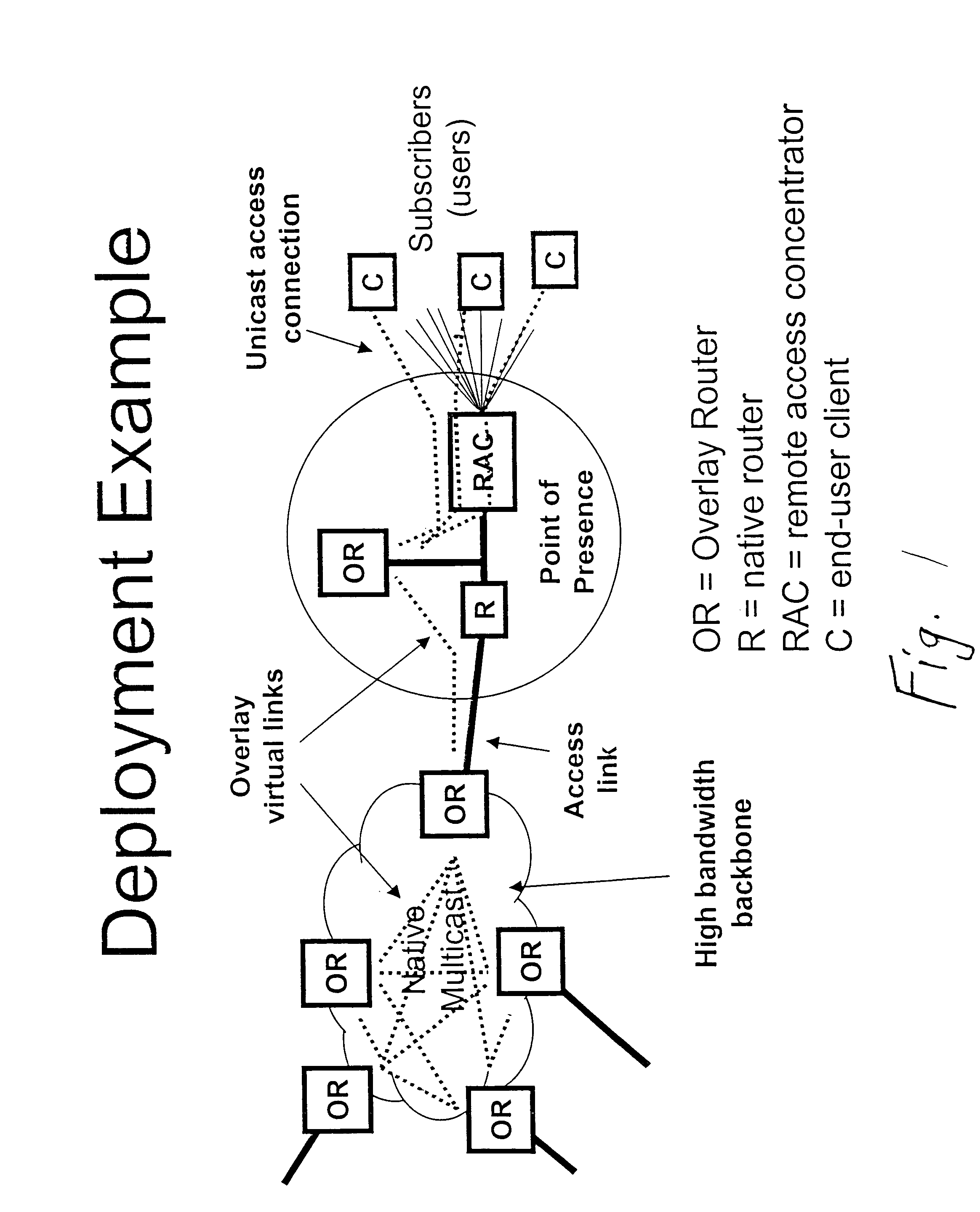
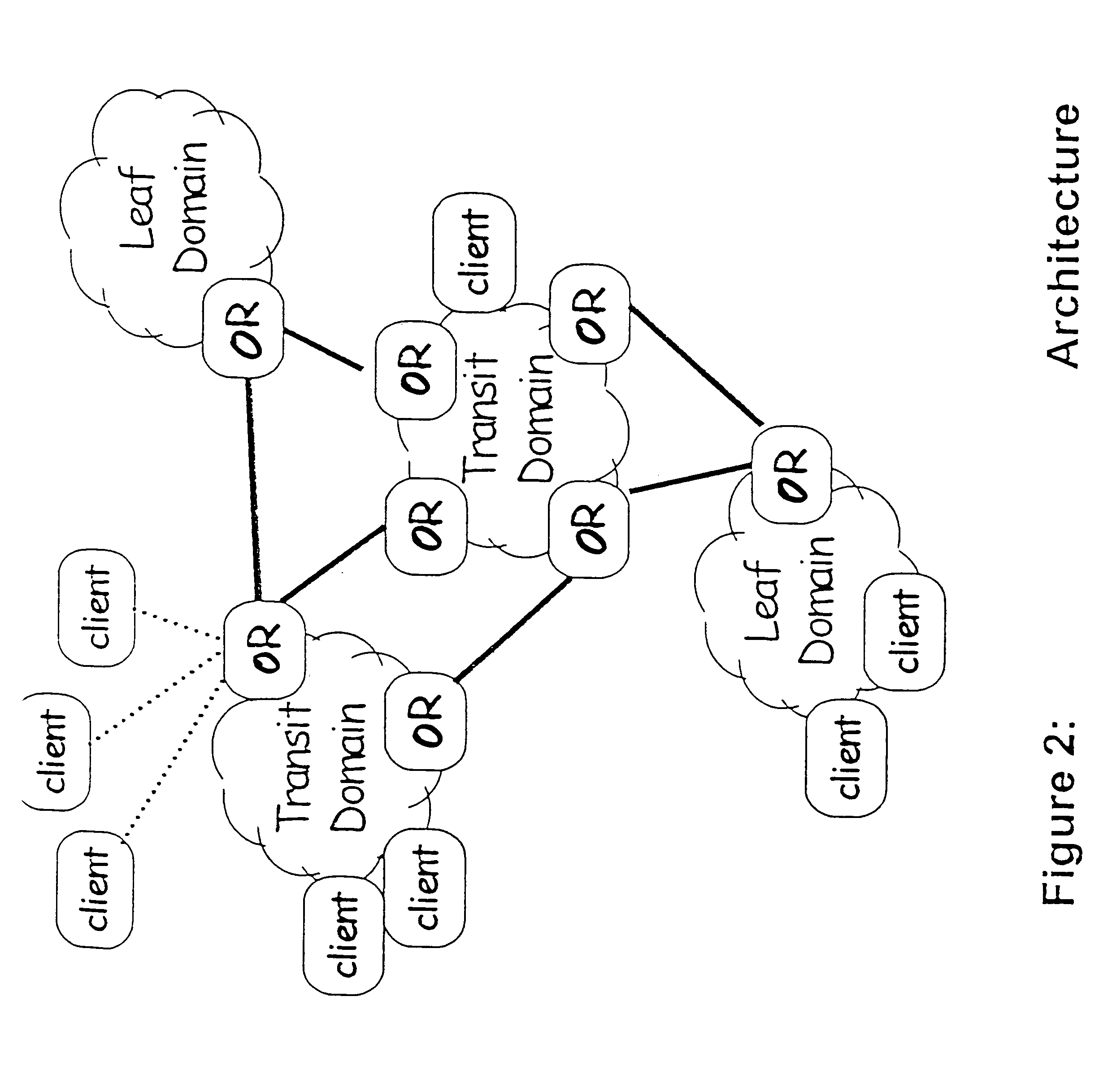
[0024]The invention uses native multicast only as a forwarding optimization where it is locally viable—typically within medium-scale, singly-administered, homogeneous network domains. In this model, the network consists of a set of isolated native multicast clouds upon which a virtual network of application-level routing agents called “overlay routers”. The overlay routers (i.e., the MediaBridge computers) implement multicast routing protocol that makes use of sophisticated application-level knowledge and management infrastructure. Unicast clients can connect...


PUM


Abstract

An overlay protocol and system for allowing multicast routing in the Internet to be performed at the application level. The overlay protocol uses “native” Internet multicast and multicast routing protocols to route information, according to overlay routing tables. Overlay groups are mapped to native multicast groups to exploit native multicasting in regional or local forwarding domains. Use of the overlay protocol allows overlay distribution to be handled in a more intelligent and bandwidth-managed fashion. Overlay routers are placed at each of several local area networks, Internet service provider's point of presence, enterprise, or other cohesively-managed locations. The overlay computers are configured according to bandwidth and security policies, and perform application-level multicast distribution across the otherwise disjoint multicast networks by using the overlay routing. The result is an overlay multicast network that is effectively managed according to local network management policies. Application-level control can be applied to the transferred data at the overlay routers.

Description

CROSS-REFERENCES TO RELATED APPLICATIONS[0001]This application is a divisional of U.S. application Ser. No. 09 / 323,869, filed Jun. 1, 1999 now U.S. Pat. No. 6,611,872, entitled “PERFORMING MULTICAST COMMUNICATION IN COMPUTER NETWORKS BY USING OVERLAY ROUTING” and claims priority from U.S. Provisional Application Ser. No. 60 / 115,454, filed Jan. 11, 1999, which are incorporated herein by reference. This application is related to the following now abandoned patent applications and / or provisional applications which are hereby incorporated by reference as if set forth in full in this specification: Provisional Patent Application Ser. No. 60 / 137,160 entitled “SYSTEM FOR BANDWIDTH ALLOCATION IN A COMPUTER NETWORK” filed on Jun. 1, 1999; and Provisional Patent Application Ser. No. 60 / 137,153 entitled “SYSTEM FOR MULTIPOINT INFRASTRUCTURE TRANSPORT IN A COMPUTER NETWORK” filed on Jun. 1, 1999.BACKGROUND OF THE INVENTION[0002]As the Internet gains in popularity it is desirable to allow broadc...

Claims


Application Information

Patent Timeline
IPC IPC(8): G06F15/173H04L12/18H04L12/56H04L45/16
CPCH04L12/1836H04L65/403H04L45/04H04L45/16H04L65/4076H04L29/06027H04L12/185H04L12/1886H04L65/611H04L65/1101
Inventor MCCANNE, STEVEN
Owner GOOGLE LLC
Why Eureka
Try Eureka