Apparatus for pumping fuel

a technology for pumping apparatus and fuel, which is applied in the direction of couplings, separation processes, braking systems, etc., can solve the problems of insufficient fuel supply, insufficient pumping capacity of suction jet pumps, and certain operating conditions, and achieves less injection molding compound, compact construction, and reduced production costs.

Inactive Publication Date: 2006-07-25
ROBERT BOSCH GMBH
View PDF11 Cites 10 Cited by
  • Summary
  • Abstract
  • Description
  • Claims
  • Application Information

AI Technical Summary

Benefits of technology

[0007]The apparatus for pumping fuel according to the invention has the advantage over the prior art that in a simple way, an improvement is attained such that the production costs are reduced by providing that the drive nozzles are surrounded by a single collection conduit, narrowing conically in the flow direction and located upstream of the mixing conduits. In this way, the suction jet pumps are more compactly constructed and can be manufactured with less injection-molding compound.
[0008]Other advantageous refinements of and improvements to the apparatus defined by the main claim are disclosed. It is especially advantageous if between the drive nozzles and the collection conduit, an annular gap is provided, which is in communication upstream with an intake conduit. In this way, the aspirated fuel flows virtually parallel to the propellant streams into the collection conduit, so that a deflection of the propellant streams transversely to the flow direction is avoided.
[0009]It is also advantageous if the collection conduit defines an intake chamber and directs the fuel out of the intake chamber into the mixing conduits, since the propellant streams generate an underpressure in the intake chamber and in this way aspirate fuel into the intake chamber via the intake conduit. The aspirated fuel is entrained by the propellant streams into the mixing conduits.

Problems solved by technology

Apparatuses for pumping fuel with a single suction jet pump, as shown for instance in German Patent DE 43 38 504 C2, have the disadvantage that the pumping capacity of the suction jet pump, under certain operating conditions, is insufficient to supply a feed pump, located in a reservoir, with enough fuel.

Method used


Image

  • Apparatus for pumping fuel
  • Apparatus for pumping fuel
  • Apparatus for pumping fuel

Examples


Embodiment Construction

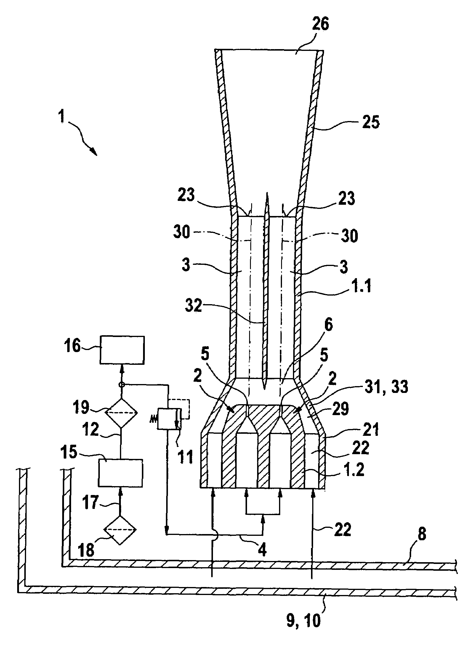
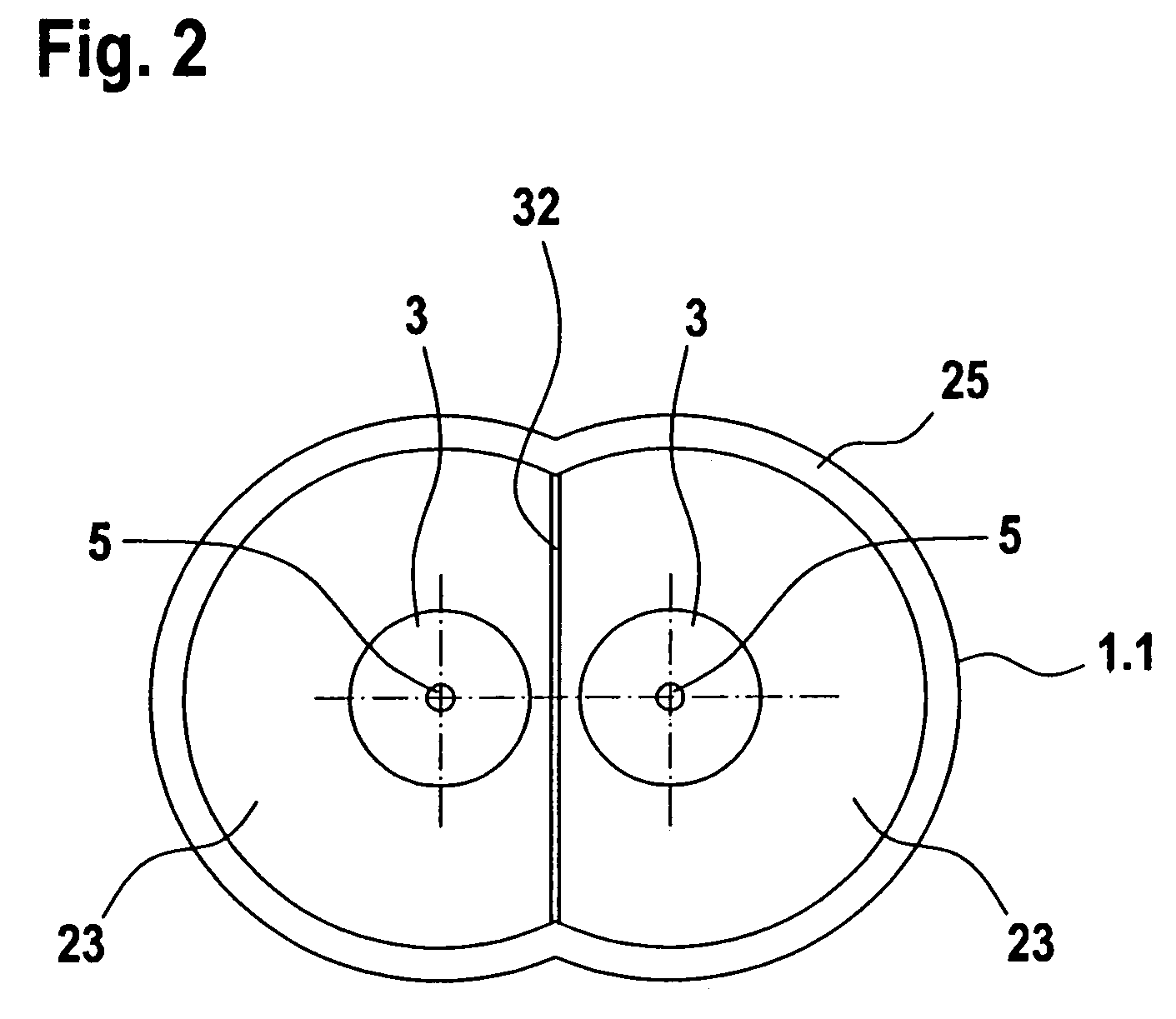
[0019]As shown in FIG. 1, the apparatus of the invention has a plurality of suction jet pumps 1, each with one drive nozzle 2 and one mixing conduit 3. The suction jet pumps 1 are provided for instance in a common housing 1.1, which is made for instance from plastic and by means of injection molding. As an example, two suction jet pumps 1 are embodied on the housing 1.1. However, it is expressly possible for there to be more than two suction jet pumps 1 integrated with the housing 1.1.

[0020]The drive nozzles 2 are embodied for instance as a nozzle-like constriction. The drive nozzles 2 communicate upstream with a propellant line 4 and downstream with a common intake chamber 6. Via the propellant line 4, each drive nozzle 2 is supplied with fuel, which reaches the intake chamber 6 in the form of a propellant stream, via one nozzle opening 5 each. The mixing conduits 3 are located downstream of the intake chamber 6.

[0021]The housing 1.1 with the suction jet pumps 1 is located for inst...


PUM

PropertyMeasurementUnit
pressure energyaaaaaaaaaa
pressureaaaaaaaaaa
flow forcesaaaaaaaaaa

Abstract

Known apparatuses for pumping fuel have at least two suction jet pumps, which each have one drive nozzle and one collection conduit and mixing conduit located downstream of the drive nozzle. A disadvantage is that the parallel suction jet pumps require a large amount of installation space, are embodied very massively, and therefore require a large amount of injection-molding compound for their manufacture. In the apparatus of the invention, the production costs and the required installation space for the suction jet pumps are reduced. According to the invention, the drive nozzles are surrounded by a single collection conduit, narrowing conically in the flow direction and located upstream of the mixing conduits.

Description

CROSS-REFERENCE TO RELATED APPLICATIONS[0001]This application is based on German Patent Applications 10 2004 029 527.1 filed Jun. 18, 2004 and 10 2004 047 782.5 filed Oct. 1, 2004, upon which priority is claimed.BACKGROUND OF THE INVENTION[0002]1. Field of the Invention[0003]The invention is directed to an improved fuel pumping apparatus, and more particularly to such an apparatus for pumping fuel to an internal combustion engine.[0004]2. Description of the Prior Art[0005]An apparatus for pumping fuel known from German patent Disclosure DE 42 19 516 A1, has at least two suction jet pumps, which each have one drive nozzle and one collection conduit and mixing conduit located downstream of the drive nozzle.[0006]Apparatuses for pumping fuel with a single suction jet pump, as shown for instance in German Patent DE 43 38 504 C2, have the disadvantage that the pumping capacity of the suction jet pump, under certain operating conditions, is insufficient to supply a feed pump, located in a...

Claims


Application Information

Patent Timeline
Patent Type & Authority Patents(United States)
IPC IPC(8): F02M37/10F02M37/04F04F5/46
CPCF04F5/466Y10T137/86075Y10T137/87265
Inventor KLEPPNER, STEPHANBRAUN, HANS-PETERWIELAND, THOMASKUERMANN, LUDGERECKART, WINFRIED
Owner ROBERT BOSCH GMBH
Why Eureka
Try Eureka