Fuel tank venting system

a fuel tank and venting technology, applied in the direction of functional valve types, containers, transportation and packaging, etc., can solve the problems of not allowing fuel vapors into the atmospher

Inactive Publication Date: 2006-07-25
COUNTRY INDS TECH
View PDF4 Cites 14 Cited by
  • Summary
  • Abstract
  • Description
  • Claims
  • Application Information

AI Technical Summary

Benefits of technology

[0013]Accordingly, it is an object of the present invention to provide a fuel tank venting system to prevent fuel vapors from being vented to the atmosphere, while allowing atmospheric air to enter the fuel tank for the purpose of fuel flow to an engine.

Problems solved by technology

When the vacuum ceases, the vent diaphragm returns to its original sealing position, which does not allow fuel vapors into the atmosphere.

Method used


Image

  • Fuel tank venting system
  • Fuel tank venting system
  • Fuel tank venting system

Examples


second embodiment

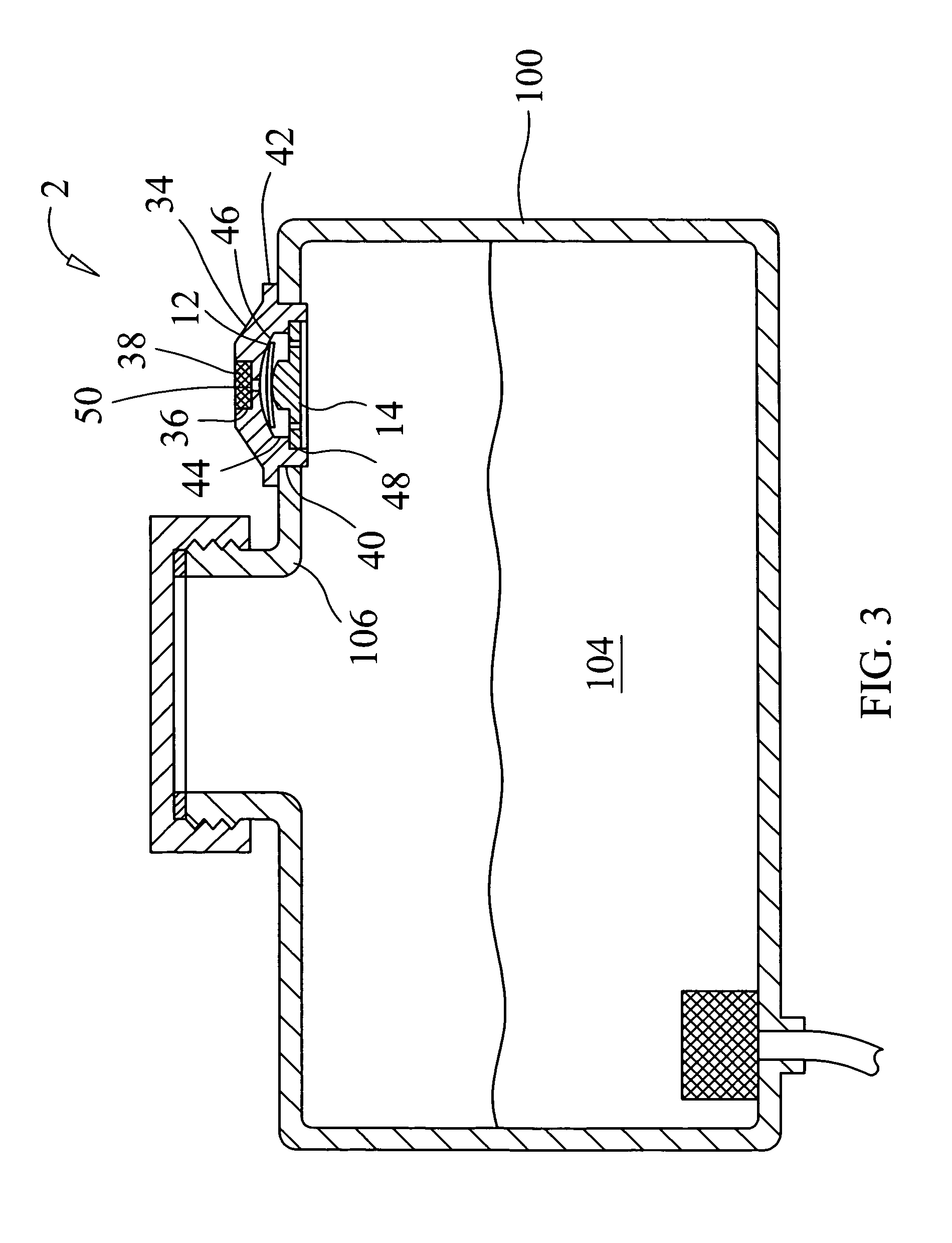
[0023]the fuel tank venting system 2 includes a vent body 34, the vent diaphragm 12 and the vent disc 14. A filter cavity 36 is preferably formed in a top of the vent body 34 to receive the air filter 38. A body opening 40 is formed through a wall 106 of a fuel tank 100 that is sized to receive an outer perimeter of the vent body 34. A flange 42 preferably extends from a perimeter of the vent body 34. The vent body 34 may be attached to the fuel tank 100 by welding, threading or any other suitable process. A valve cavity 44 with a substantially concave bottom 46 is formed in a bottom of the vent body 34. A flow passage 50 is formed through the filter cavity 36 to the substantially concave bottom 46. A disc counter bore 48 is formed in a bottom of the vent body 34 to receive an outer perimeter of the vent disc 14.

[0024]The vent diaphragm 12 is first inserted into the valve cavity 44. The vent disc 14 is then inserted into the disc counter bore 48. The vent disc 14 is retained in the ...

third embodiment

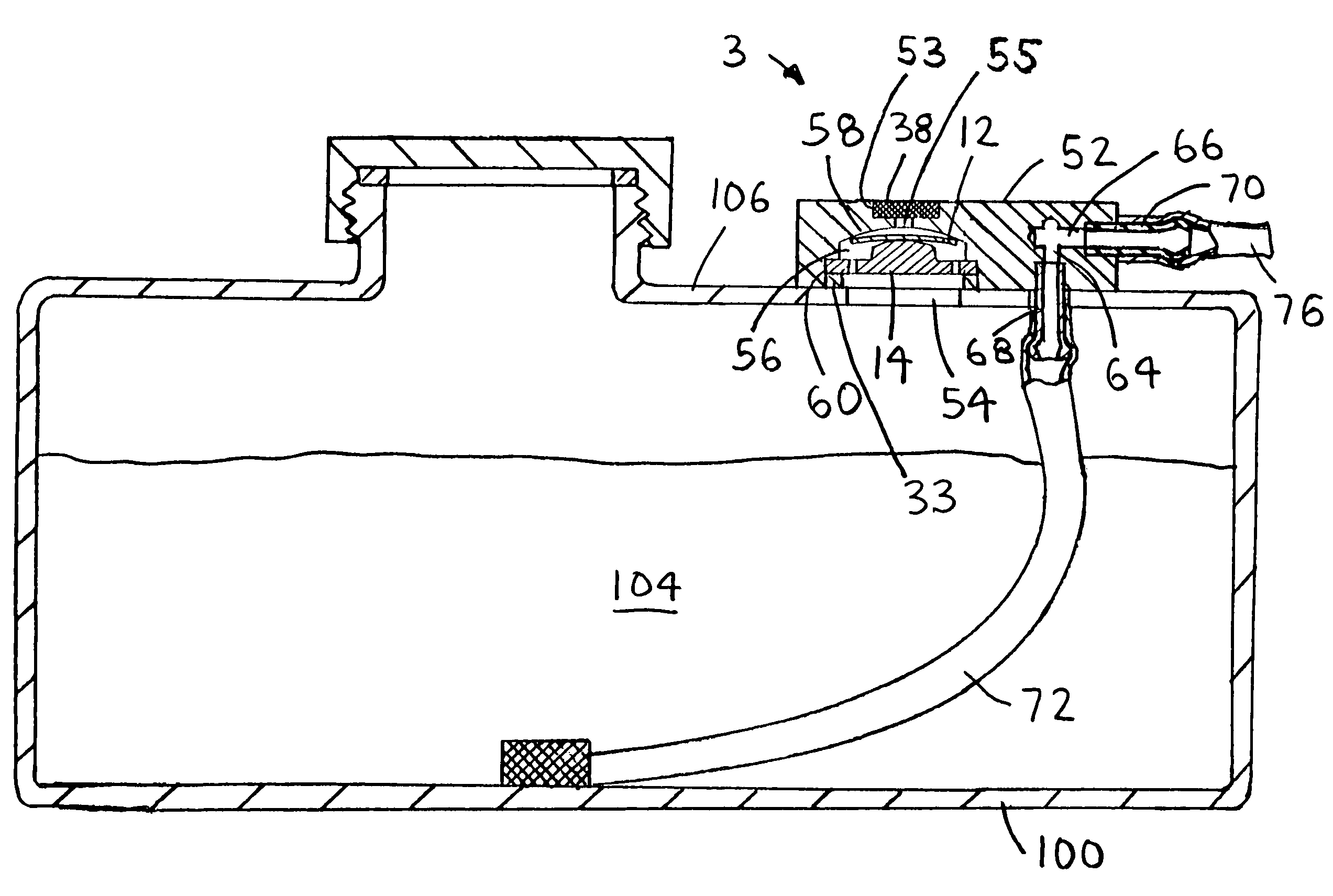
[0026]the fuel tank venting system 3 includes a fuel vent body 52, the vent diaphragm 12 and the vent disc 14. A filter cavity 53 is preferably formed in a top of the fuel vent body 52 to receive the air filter 38. The fuel vent body 52 is attached to the fuel tank 100 with any suitable process. A clearance opening 54 is preferably formed in a wall 106 of the fuel tank 100 that is sized to allow air flow through the vent disc 14. A valve cavity 56 with a substantially concave bottom 58 is formed in a bottom of the fuel vent body 52. A flow passage 55 is formed through the filter cavity 53 to the substantially concave bottom 58. A disc counter bore 60 is formed in a bottom of the fuel vent body 52 to receive the disc flange 26 of the vent disc 14. The vent diaphragm 12 is first inserted into valve cavity 56. The vent disc 14 is then inserted into the disc counter bore 60. The vent diaphragm 12 is retained between the substantially concave bottom 58 of the valve cavity 56 and the subs...


PUM


Abstract

A fuel tank venting system includes a fuel cap, a vent diaphragm and a vent disc. A valve cavity with a substantially concave bottom is formed in a bottom of the fuel cap. At least one air passage is formed through the vent disc. A substantially convex surface is formed on a top of the diaphragm projection. The vent diaphragm is retained between the substantially concave bottom and the substantially convex surface. When air is needed for fuel flow, a vacuum within the fuel tank pulls the perimeter of the vent diaphragm downward, which breaks a seal with the substantially concave bottom to allow air flow. In a second embodiment, the fuel tank venting system is contained in a wall of the fuel tank. In a third embodiment, the fuel tank venting system is contained in a fuel vent body, which is attached to the fuel tank.

Description

CROSS-REFERENCES TO RELATED APPLICATIONS[0001]This is a continuation-in-part patent application taking priority from a utility patent application having Ser. No. 10 / 846,296 filed on May 14, 2004 now U.S. Pat. No. 6,866,056.BACKGROUND OF THE INVENTION[0002]1. Field of the Invention[0003]The present invention relates generally to venting fuel tanks and more specifically to a fuel tank venting system, which may be located in a fuel cap or in a wall of the fuel tank.[0004]2. Discussion of the Prior Art[0005]Fuel tanks used with small engines usually allow fuel vapors to continually vent to the atmosphere. Sometimes check valves are incorporated in the gas cap to prevent the escape of fuel vapors. Some types of check valves seal well under high pressure, but allow fuel vapor seepage under low pressure. With marine fuel tanks, a thumb screw in the fuel cap is used to seal the marine fuel tank, when not in use. The thumb screw is opened in most cases to run the engine. During the time when...

Claims


Application Information

Patent Timeline
Patent Type & Authority Patents(United States)
IPC IPC(8): F16K15/14B60K15/035F16K24/06
CPCB60K15/035F16K24/06B60K15/03519Y10T137/0491Y10T137/7897Y10T137/86324
Inventor SCOTT, WILLIAM A.
Owner COUNTRY INDS TECH
Why Eureka
Try Eureka