Transmission system for work vehicle

a technology for working vehicles and transmission systems, applied in the direction of machines/engines, mechanical equipment, transportation and packaging, etc., to achieve the effect of increasing the rotational speed of the engine, high power operation, and high power operation

Active Publication Date: 2006-07-25
KOMATSU LTD
View PDF10 Cites 5 Cited by
  • Summary
  • Abstract
  • Description
  • Claims
  • Application Information

AI Technical Summary

Benefits of technology

[0011]In the invention, when executing a downshift from a higher speed gear to a lower speed gear, the friction clutch corresponding to the higher speed gear slides so as to enable power transmission and during the sliding of the friction clutch, the engine performs high power operation (overload operation). As a result, the driving force required for the work vehicle is supplied through a power transmission line which extends from the engine to the work vehicle through the higher speed gear, and the excessive output engine torque generated in the high power operation is used for increasing the rotational speed of the engine. According to the invention, when executing a shift from a higher speed gear to a lower speed gear, the rotational speed of the engine can be increased while supplying driving torque to the downstream driving wheels and others according to work load, so that a pause due to a shortage of driving torque can be avoided and, in consequence, a shock caused by a speed change during the downshift can be alleviated. It should be noted that the above-described effects can be achieved by controlling the friction clutches and the engine with the friction clutch controlling means and the engine controlling means respectively as described earlier, so that no complicated structure is involved.
[0012]The transmission system of the invention preferably includes engine rotational speed detecting means for detecting the rotational speed of the engine. If the rotational speed of the engine detected by the engine rotational speed detecting means reaches a matching rotational speed for the lower speed gear at a shift point after a start of high power operation, the friction clutch controlling means brings the friction clutch for the higher speed gear into a disengaged condition and the friction clutch for the lower speed gear into an engaged condition, while the engine controlling means switches the operation of the engine from the high power operation to the full load operation. Accordingly, by downshifting in such a way that the rotational speed of the engine is made equal to a matching rotational speed, that is, the engine rotational speed for the lower speed gear, at a shift point where the driving performance for the higher speed gear coincides with the driving performance for the lower speed gear, the higher speed gear can be more smoothly shifted to the lower speed gear, with the result that a shock caused by a speed change during the downshift can be further mitigated.

Problems solved by technology

As a result, the driving force required for the work vehicle is supplied through a power transmission line which extends from the engine to the work vehicle through the higher speed gear, and the excessive output engine torque generated in the high power operation is used for increasing the rotational speed of the engine.

Method used


Image

  • Transmission system for work vehicle
  • Transmission system for work vehicle
  • Transmission system for work vehicle

Examples


Embodiment Construction

[0019]Referring now to the accompanying drawings, a transmission system for a work vehicle will be concretely described according to a preferred embodiment of the invention. Note that this embodiment is associated with a case where the invention is applied to a bulldozer that serves as a work vehicle.

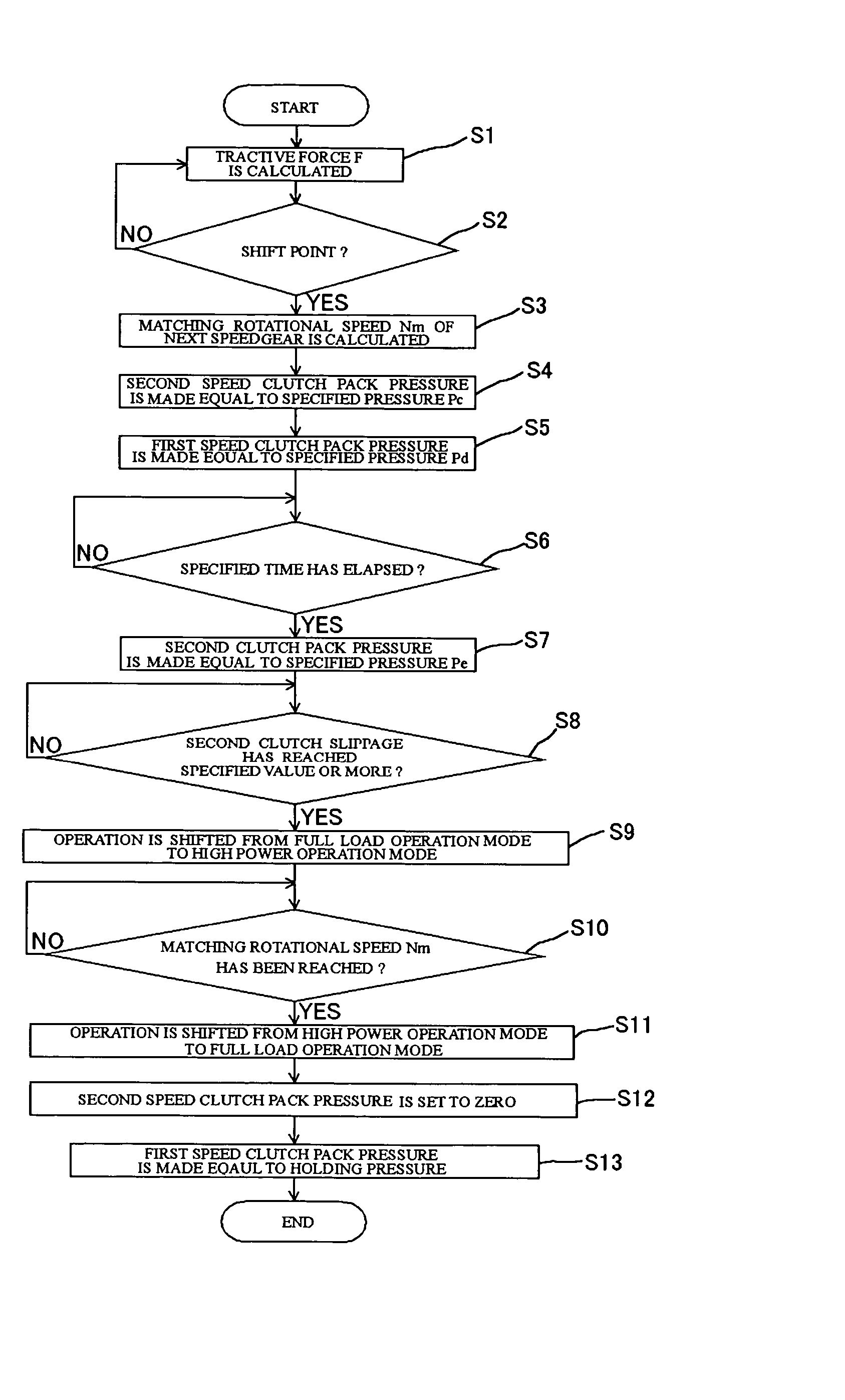
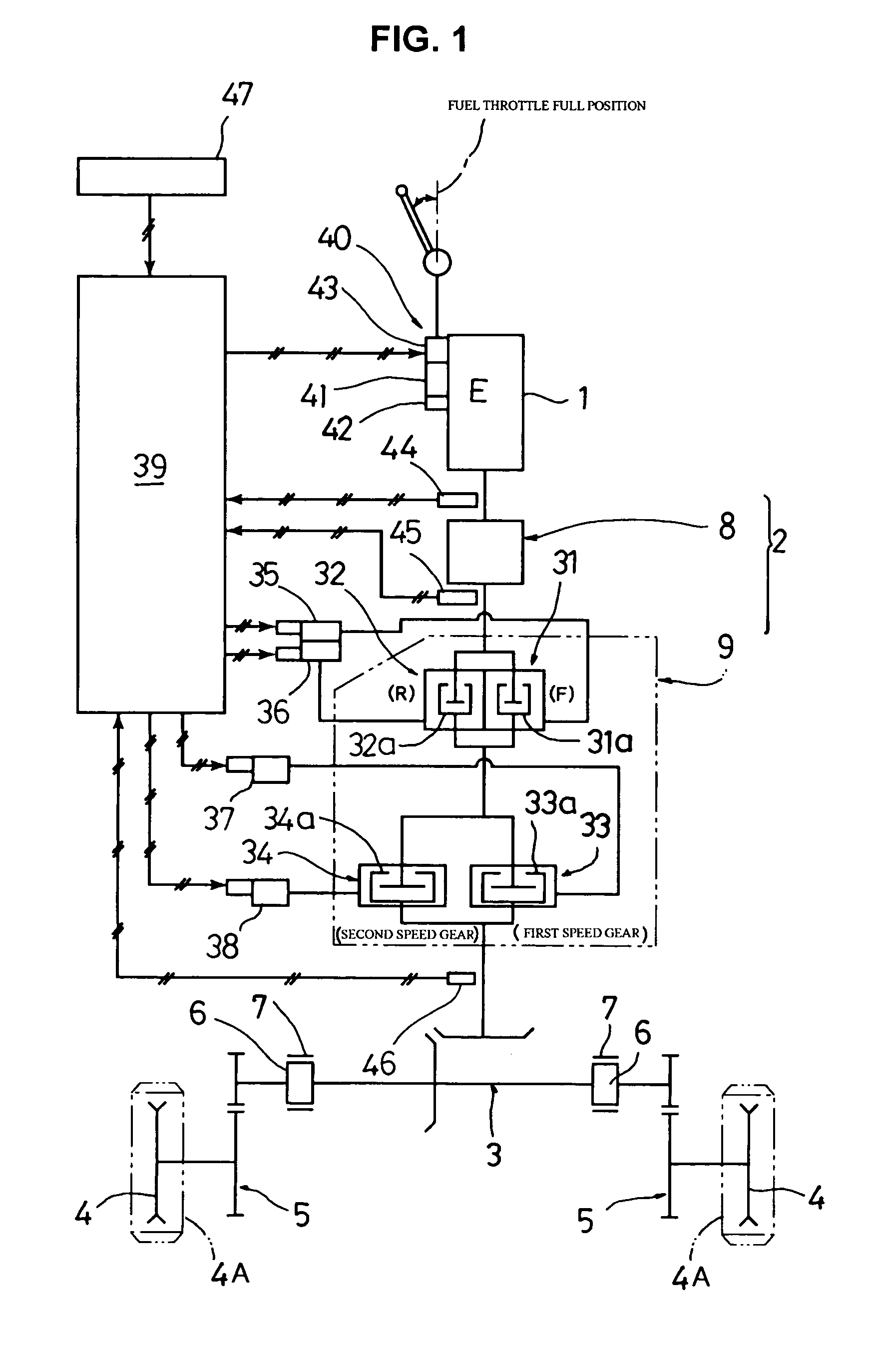
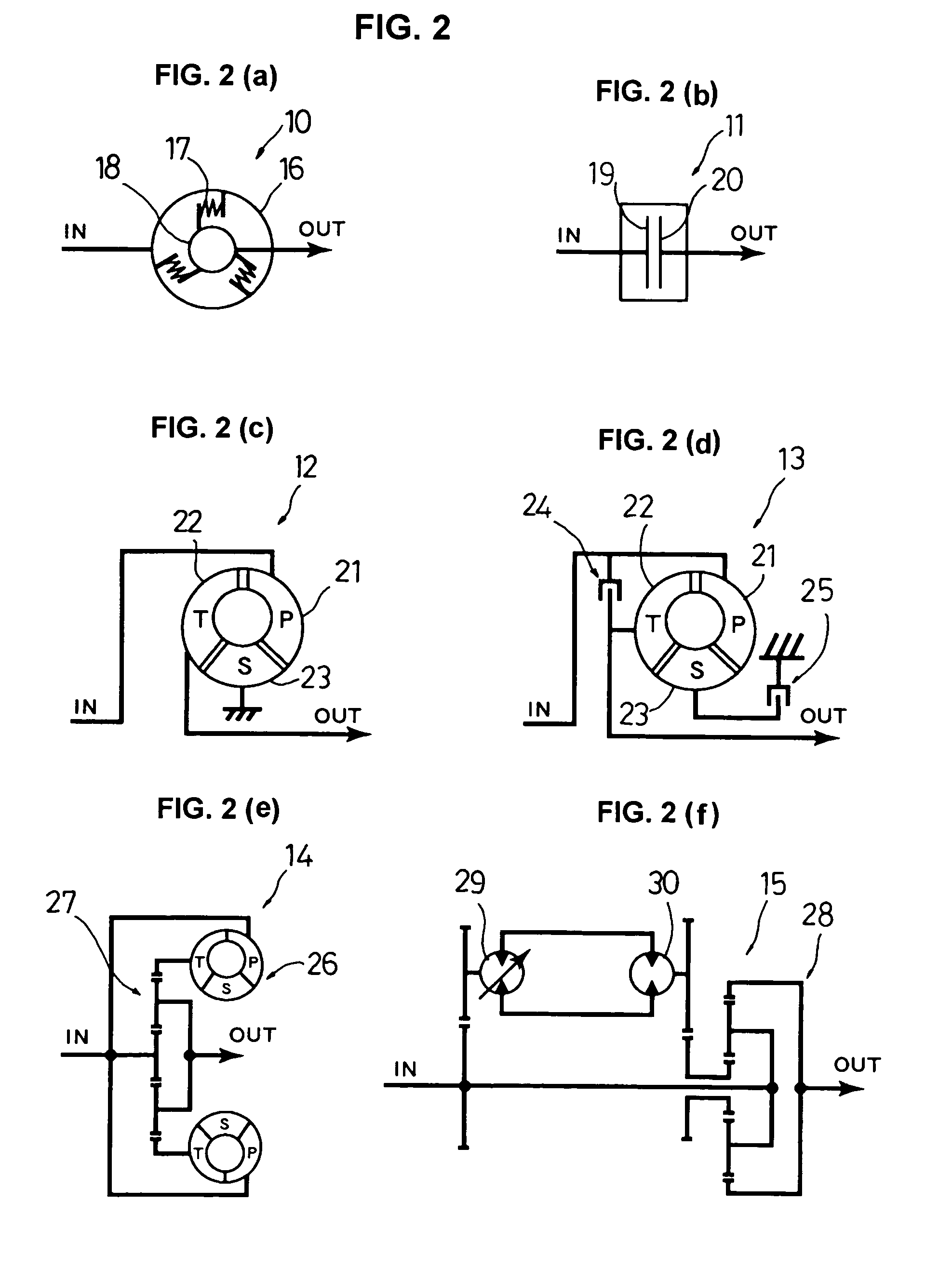
[0020]FIG. 1 shows a block diagram of the transmission system according to the embodiment of the invention. FIG. 2 shows a diagrammatical view illustrating various elements that constitute an input unit.

[0021]The bulldozer (hereinafter referred to as “vehicle”) of this embodiment includes a tractor unit which is driven with such a mechanism that the output of a diesel engine (hereinafter referred to as “engine”) is transmitted to right and left sprockets (driving wheels) through a power transmission to allow rotational movement of crawler belts which respectively mesh with the sprockets; a blade located in front of the tractor unit; and a ripper located behind the tractor unit (these me...


PUM


Abstract

A transmission system for a work vehicle, which is capable of reliably mitigating, with relatively simple arrangement, shocks caused by speed changes even in a work vehicle such as a bulldozer in which almost all operations are performed with the engine operating at full load. In the transmission system which converts the output torque of an engine into torque according to work load by operations for shifting speed gears through disengagement/engagement of friction clutches, if a downshift from a higher speed gear to a lower speed gear is effected while the engine operating at full load, the friction clutch controlling valves, controller and friction clutches allows the friction clutch corresponding to the higher speed gear to slide so as to enable power transmission and the engine controlling fuel injection system and controller allows the engine to perform high power operation (overload operation) during the sliding of the friction clutch.

Description

TECHNICAL FIELD[0001]The invention relates to a transmission system mainly mounted on a work vehicle such as a bulldozer and agricultural tractor and more particularly to a transmission system for a work vehicle having a function of mitigating shocks caused by speed changes.BACKGROUND ART[0002]Taking bulldozers for example, vehicles equipped with a power train designed to directly transmit the output of the engine to the transmission (gear shifter) through a main clutch (the vehicles of this type are hereinafter referred to as “direct-drive vehicles”) have superior power transmission efficiency, but require the operator driving skill of a certain level for effective operation because the load imposed on the vehicle needs to be controlled by operating the implement or the gear shifter. In contrast with this, vehicles equipped with a power train designed to transmit the output of the engine to the transmission through a torque converter (the vehicles of this type are hereinafter refer...

Claims


Application Information

Patent Timeline
Patent Type & Authority Patents(United States)
IPC IPC(8): F16H61/26B60W10/06B60W10/04B60W10/10B60W10/11F02D29/00F16H59/24F16H59/42F16H61/04F16H61/08F16H61/68F16H61/684F16H63/40F16H63/50
CPCB60W10/06B60W10/11B60W30/18F16H61/0437B60K2741/065B60Y2200/221Y10T477/693636F16H63/502F16H2306/48Y10T477/69364Y10T477/638B60W10/04B60W30/1819
Inventor NAKAGAWA, TOMOHIROYAMAMOTO, SHIGERUOKADA, TOSHIKAZU
Owner KOMATSU LTD
Why Eureka
Try Eureka