Method for manufacturing a rotatable plug element and valve

a technology of rotatable plug elements and valves, which is applied in the field of valve construction, can solve the problems of valve housings, valve manufacturing tools, and overall cost of such valves, and achieve the effect of effective sealing

Inactive Publication Date: 2006-07-25
ROBERTSHAW CONTROLS CO
View PDF17 Cites 47 Cited by
  • Summary
  • Abstract
  • Description
  • Claims
  • Application Information

AI Technical Summary

Benefits of technology

[0008]The present invention provides a gas valve that includes a conical rotatable plug component that is received in a conical cavity formed in a valve body wherein neither the surface of the plug nor the surface of the cavity require machining in order to achieve an effective seal therebetween. Moreover, the configuration of the valve permits the use of molded plastic rather than cast metal in the construction of the plug. The plug serves to establish a flow path through the valve body when rotated so as to align an opening formed in the cavity wall with an orifice formed in the side of the plug. A rotational orientation in which there is no overlap between the opening in the wall and the orifice in the plug shuts off all flow through the valve.

Problems solved by technology

A side effect of such requirement is that it also typically serves to limit the type of materials that are used in the construction of such valves.
The failure of gaskets or seals used in the interior of such valves to control the flow of gas through the valve would at worst merely result in the flow of additional gas to the burner where its combustion is adequately provided for and where it would thus not pose an additional hazard during a fire.
The use of metals and the machining of the various components significantly contribute to the overall cost of such valve.
Even minor variations in the machining process contribute to a high rejection rate that further affects the overall cost of manufacture.

Method used


Image

  • Method for manufacturing a rotatable plug element and valve
  • Method for manufacturing a rotatable plug element and valve
  • Method for manufacturing a rotatable plug element and valve

Examples


Embodiment Construction

[0019]The valve of the present invention is especially suited for controlling the flow of a combustible gas to gas-fired appliances such as a furnace, water heater or gas-burning fireplace. The valve configuration obviates the need to rely on machined surfaces in order to establish seals between moving parts within the valve and further allows the use of plastic in the construction of certain components within the valve.

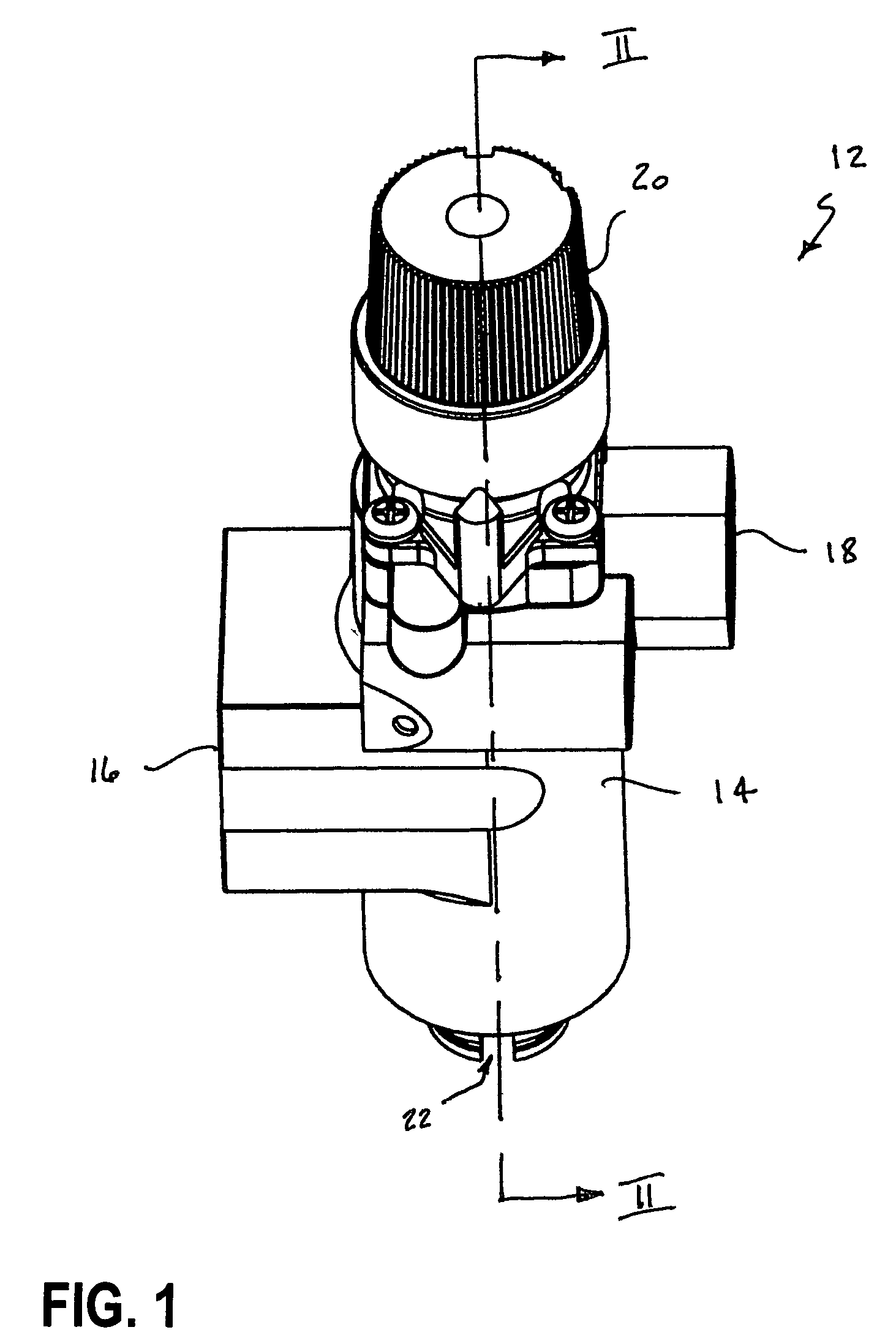
[0020]FIG. 1 is a perspective view of a valve of the present invention. The valve 12 includes a valve body 14, an inlet port 16 and an outlet port 18. Control knob 20 is rotatable and depressible to enable manual actuation of the valve. In the particular embodiment shown, a thermocouple-powered electromagnet is insertable into a bore 22 formed at the base of the valve body.

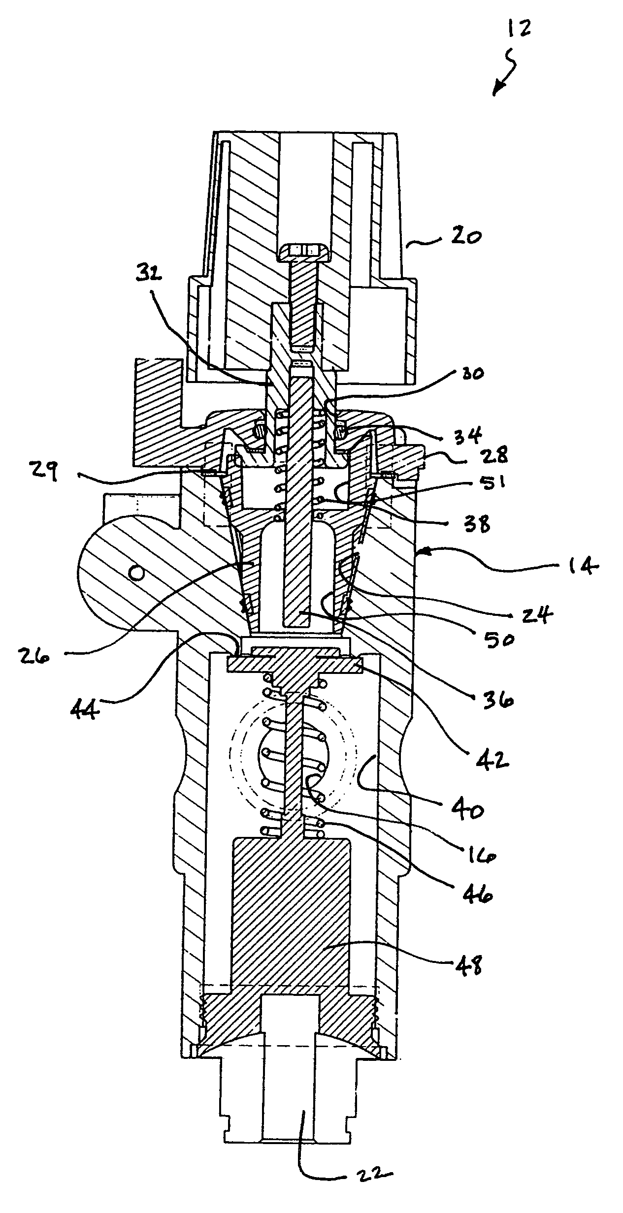
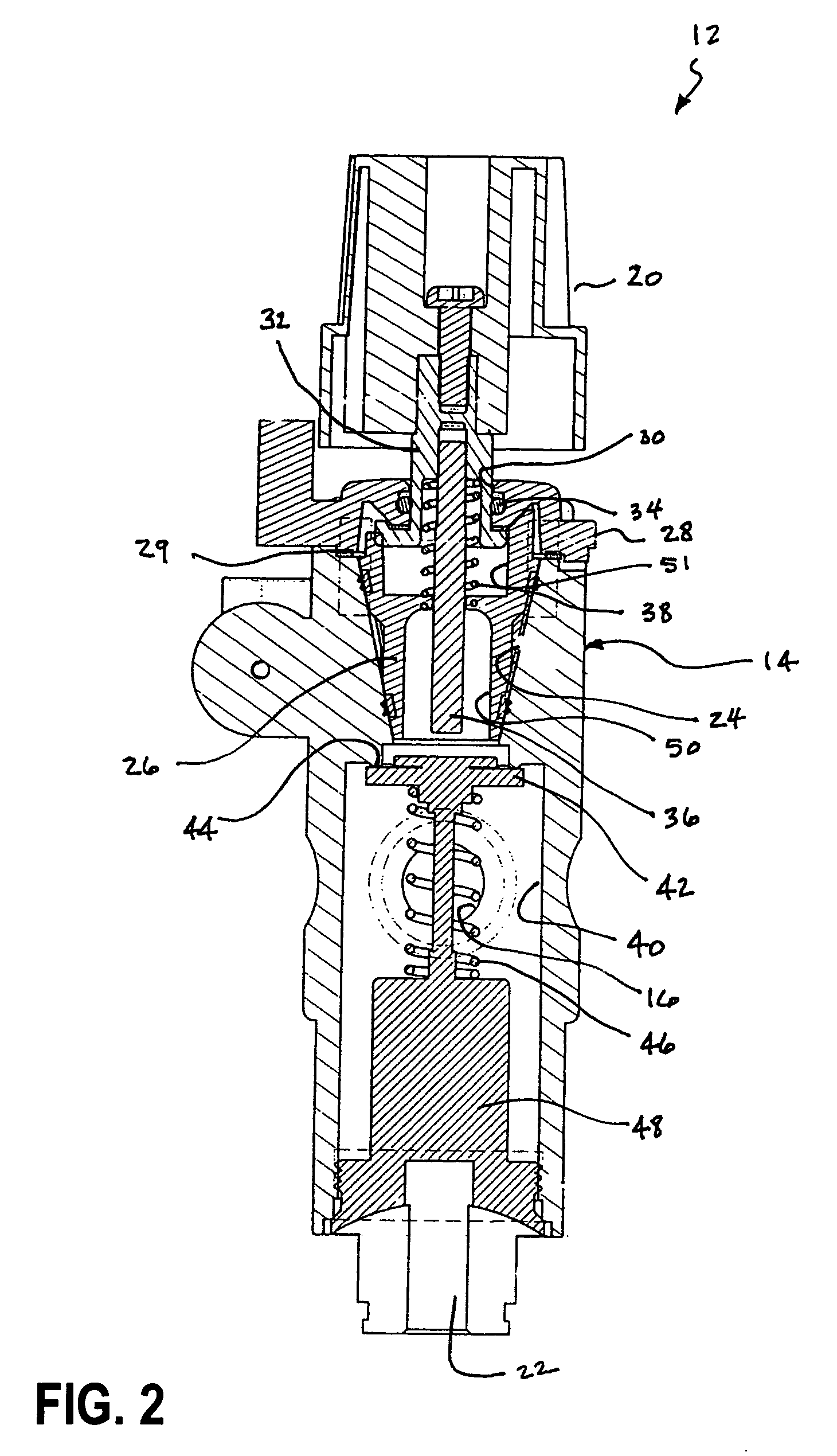
[0021]FIG. 2 is a cross-sectional view of the valve shown in FIG. 1 taken along lines II—II. A conical cavity 24 is formed in the valve body 14 and is dimensioned to receive rotatable plug element ...


PUM

PropertyMeasurementUnit
temperaturesaaaaaaaaaa
depthaaaaaaaaaa
temperaturesaaaaaaaaaa

Abstract

A valve for controlling the flow of a gas therethrough which requires no machining in order to attain an effective seal between the valve seating surface and a rotatable plug element. The valve seat surface remains as cast while the plug consists of an overmolded plastic. The overmolding defines an array of pliable sealing ridges. The use of overmolding facilitates the use of cost-saving plastic materials, and obviates the need for expensive machining of the cooperating surfaces.

Description

CROSS REFERENCE TO RELATED APPLICATION[0001]This patent application is a continuation application of U.S. patent application Ser. No. 09 / 684,450 filed Oct. 6, 2000, now abandoned.BACKGROUND OF THE INVENTION[0002]The present invention generally relates to the construction of valves such as are used to control the flow of combustible gas-to-gas-fired appliances and more particularly pertains to improvements in the configuration and construction of such valves in order to reduce the cost of their manufacture.[0003]Regulating authorities typically mandate that valves that are to be used to control the flow of a combustible gas to a gas-fired appliance, such as for example a furnace, water heater or gas-burning fireplace, must be capable of maintaining their integrity when subjected to high temperatures such as may be encountered during a fire so as to preclude the external leakage of gas. This is intended to prevent a fire from being aggravated by the supply of additional fuel leaking f...

Claims


Application Information

Patent Timeline
Patent Type & Authority Patents(United States)
IPC IPC(8): B29C45/14A61M39/00F16K5/02F16K5/04F16K5/06F16K27/06
CPCF16K5/0214F16K27/06F16K5/0278B29C2045/14459Y10S164/13
Inventor KHOURY, DAVID
Owner ROBERTSHAW CONTROLS CO
Why Eureka
Try Eureka