Fiber-based displays containing lenses and methods of making same

Inactive Publication Date: 2006-07-25
MOORE CHAD BYRON
View PDF45 Cites 32 Cited by
  • Summary
  • Abstract
  • Description
  • Claims
  • Application Information

AI Technical Summary

Benefits of technology

[0016]It is a primary object of the present invention to create a three-dimensional display where the image is created by dynamically varying the distance of the image from the viewer pixel by individual pixel. The resolution of the depth of the image is increased by applying the address voltage to more than one address electrode in at least one pixel location

Problems solved by technology

This makes it difficult to obtain bright images.
Prior art techniques for generating a three-dimensional image or multiple view image required a difficult alignment of either the lens array sheet or

Method used


Image

  • Fiber-based displays containing lenses and methods of making same
  • Fiber-based displays containing lenses and methods of making same
  • Fiber-based displays containing lenses and methods of making same

Examples


Embodiment Construction

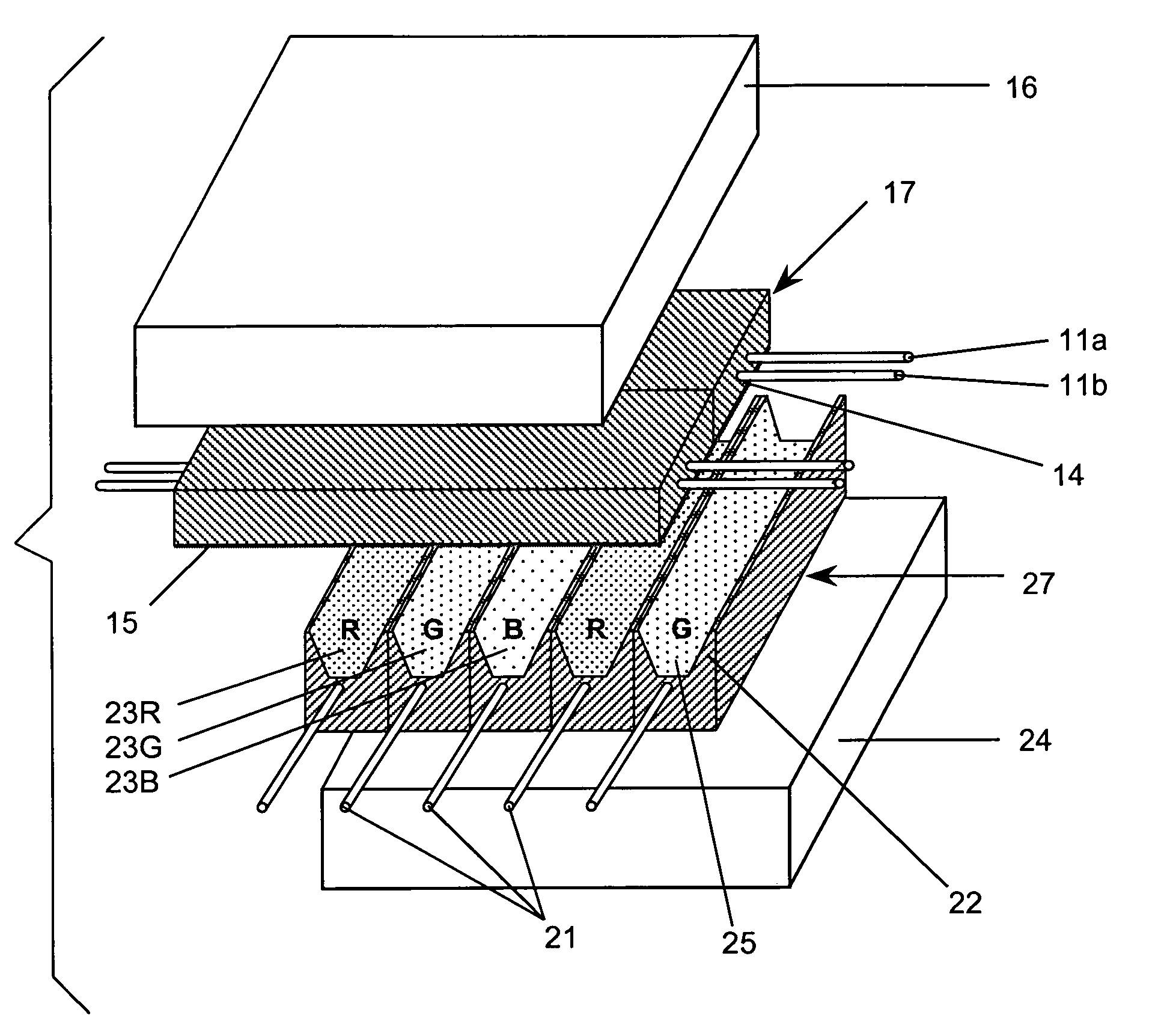
[0071]Since most of the lens arrays are linear arrays of lenses, such as a lenticular lens array, and most electronic displays are linear arrays of image elements, it is an object of this invention to combine these two functions into an array of individual fibers. The individual fibers contain the lens or optical function and at least one set of electrodes. Containing the lens function and the address electrode in the same fiber assures alignment of each pixel with its representative lens system.

[0072]Plasma and plasma addressed liquid crystal displays are the primary focus of most of the following embodiments, however, the disclosure is applicable to field emission displays (FED), cathode ray tubes (CRT), electroluminescent (EL) displays or any type of similar display.

[0073]An issued U.S. Pat. No. 5,984,747, the disclosure of which is incorporated herein by reference and co-pending U.S. patent application Ser. No. 09 / 299,370, the disclosure of which also is incorporated herein by r...


PUM


Abstract

The invention relates to an electronic display that combines the optical function of the display and part of the electronic function of the display into an array of individual fibers. The individual fibers contain a lens or optical function and at least one set of electrodes. Containing the lens function and the address electrode in the same fiber assures alignment of each pixel with its representative lens system and allows for the fabrication of very large three-dimensional, direct view displays. The electronic part of the displays can function as a plasma display (PDP), plasma addressed liquid crystal (PALC) display, field emission display (FED), cathode ray tube (CRT), electroluminescent (EL) display or any similar type of display.

Description

REFERENCE TO RELATED APPLICATIONS[0001]The present application is a continuation-in-part of U.S. patent application Ser. No. 09 / 299,370, filed on Apr. 26, 1999, entitled “FIBER-BASED PLASMA DISPLAYS”, now U.S. Pat. No. 6,414,433 which is a Continuation in Part of U.S. patent application Ser. No. 08 / 810,960, filed on Feb. 27, 1997, now U.S. Pat. No. 5,984,747, the disclosures of which are incorporated herein by reference.FIELD OF THE INVENTION[0002]The invention pertains to fiber-based displays with built-in lenses and their methods of manufacture. More particularly, the invention pertains to three-dimensional and multiple view displays, and fabricating such displays using fibers.BACKGROUND OF THE INVENTION[0003]All electronic display technologies are composed of a large array of display picture elements, called pixels, arranged in a two-dimensional matrix. Color is added to these displays by subdividing each pixel element into three-color subpixels. The electronic display technologi...

Claims


Application Information

Patent Timeline
IPC IPC(8): G02B6/32
CPCG02B6/0011
Inventor MOORE, CHAD BYRON
Owner MOORE CHAD BYRON
Why Eureka
Try Eureka