Optical fiber cable with retaining sheath

a technology sheaths, which is applied in the direction of optics, fibre mechanical structures, instruments, etc., can solve the problems of micro-cables or mini-cables buckling, and achieve the effects of reducing the coefficient of friction of cables, increasing the stiffness of optical fiber telecommunications cables, and facilitating linear retention of cables

Inactive Publication Date: 2006-07-25
SILEC CABLE
View PDF16 Cites 36 Cited by
  • Summary
  • Abstract
  • Description
  • Claims
  • Application Information

AI Technical Summary

Benefits of technology

[0014]The main object of the present invention is to reduce the friction on an optical fiber cable when installed in a conduit, in particular by a blowing or floating technique, whilst preserving the cohesion of the diverse members of the cable and a highly compact cable, and without degrading transmission quality and the service life of the optical fibers in the cable.
[0016]Since the external layer is the member of the cable that may be in direct contact with the wall of a microconduit or miniconduit, reducing the coefficient of friction of the cable by choosing a coefficient of friction of the external layer lower than that of existing retaining sheaths reduces the traction forces exerted on the cable during installation by a blowing or floating technique.
[0017]As will emerge hereinafter, the thickness of the external layer is a few tens of millimeters and thus of the same order as the thickness of the retaining sheath, which produces a very compact cable. The cable is even more compact if the optical fibers are clamped in the retaining sheath by mechanical coupling with the latter or by way of retaining sheaths enclosing optical fiber modules and by mechanical coupling of the external layer and the retaining sheath surrounded by the external layer.
[0018]A second object of the invention is to increase the stiffness of the optical fiber telecommunication cable in order to facilitate the linear retention of the cable in a microconduit or a miniconduit over a distance from tens to hundreds of meters, at the same time as avoiding curvatures or bendings of the assembly comprising the retaining sheath and the external layer leading to a bunching effect. To this end, the stiffness of the external layer is greater than the stiffness of the retaining sheath surrounded by the external layer.
[0019]It will be noted that merely replacing an external retaining sheath of a prior art minicable or microcable by an external layer according to the invention would bring the optical fibers into contact with a material that would be too stiff and hard, which would give rise to a risk of stressing of the optical fibers that could be reflected in mechanical damage of the optical fibers and / or degraded optical signal transmission performance in the optical fibers. The interposition of the retaining sheath between the optical fibers, or optical fiber modules, and the external layer according to the invention produces a damping effect for the optical fibers in relation to stresses exerted on the external layer.

Problems solved by technology

Moreover, the retaining sheath offers a low stiffness which causes the microcable or minicable to buckle, an effect which becomes more accentuated as the length of the microconduit or miniconduit increases.

Method used


Image

  • Optical fiber cable with retaining sheath
  • Optical fiber cable with retaining sheath
  • Optical fiber cable with retaining sheath

Examples


second embodiment

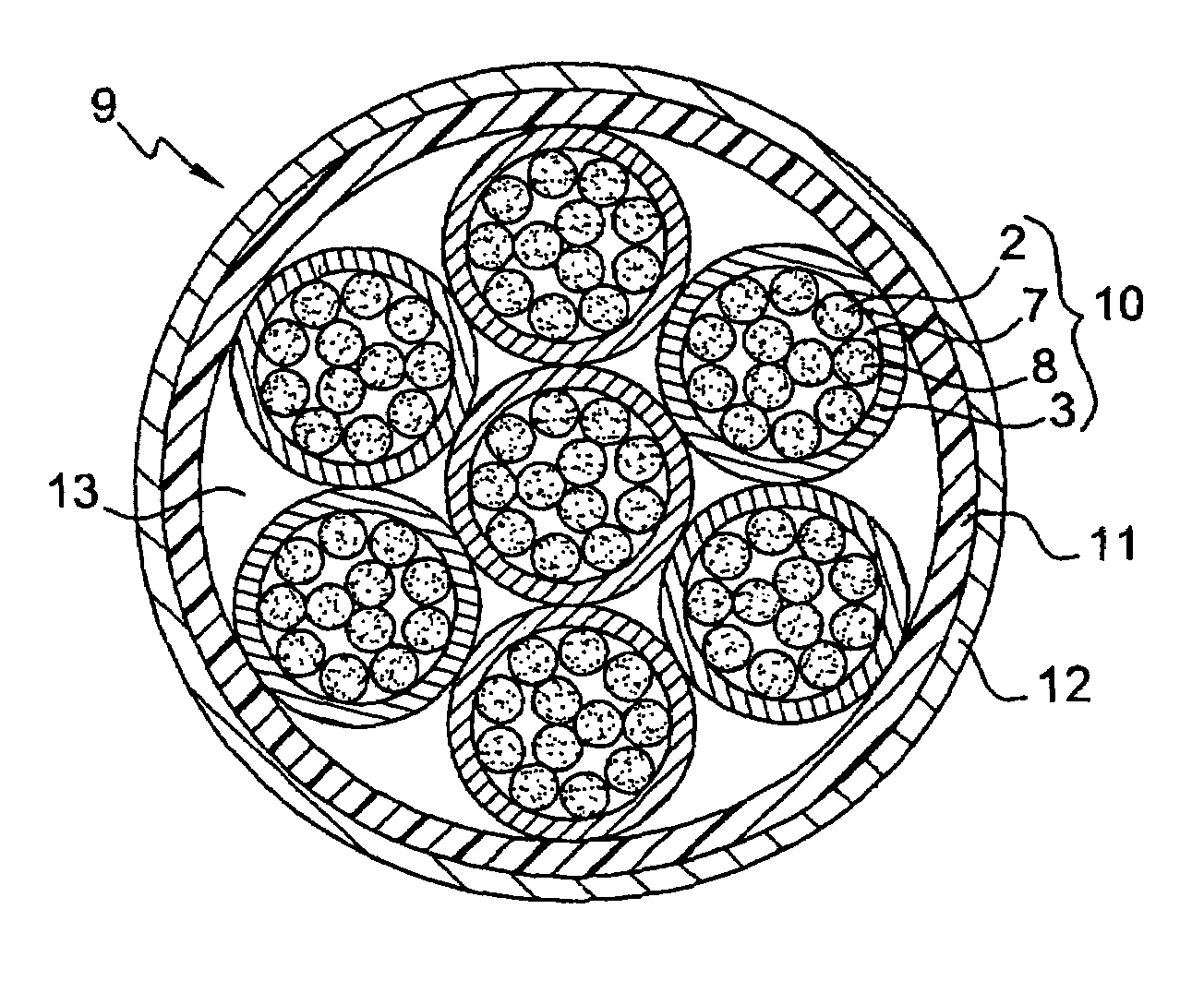
[0069]In the invention, a telecommunication cable constitutes an optical fiber minicable 9 analogous to a supermodule as disclosed in International Patent Application No. WO 02 / 31568, but with an external layer conforming to the invention. The minicable 9 comprises a plurality of optical fiber modules 10, for example seven such modules, as shown in FIG. 9, and more generally at least two optical fiber modules 10. The relatively low number of modules 10 in the minicable 9 means that the modules can easily be distinguished from each other.

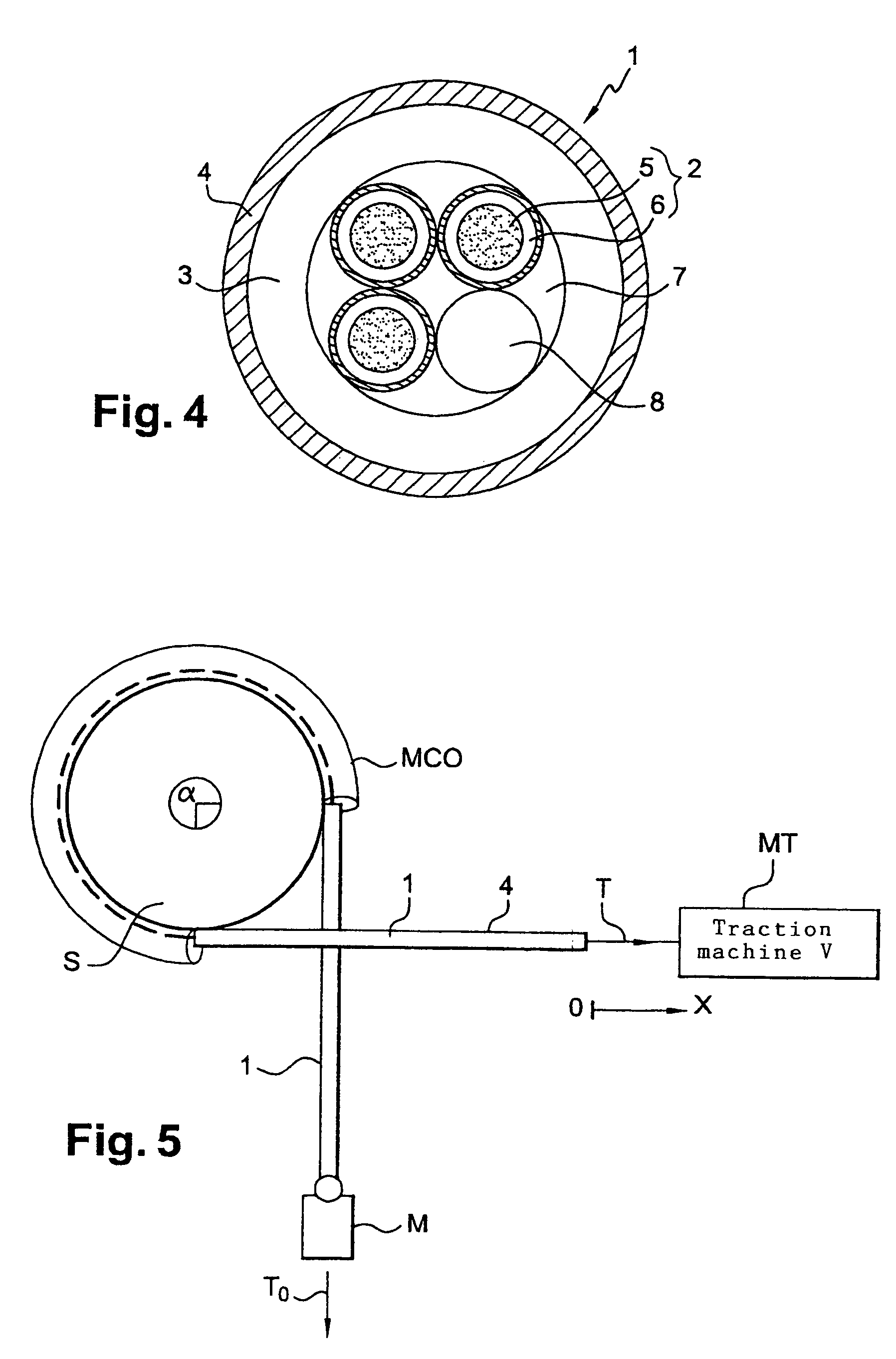
[0070]Each optical fiber module 10 constitutes a microcable analogous to that shown in FIG. 4, but with no external layer 4. Thus each module 10 comprises a plurality of optical fibers 2 each having a silica core 5 covered with a colored identification layer 6 and a “microsheath” type retaining sheath 3 that has low thickness, that is easy to tear and that is mechanically coupled to all of the optical fibers that it contains in order to clamp them. A...

first embodiment

[0071]As in the first embodiment, shown in FIG. 4, a module 10 may contain a filling material 7 used as a sealing product and one or more mechanical reinforcing fibers 8, for example two reinforcing fibers per ten optical fibers per module. The filling material 7 fills all of the space between the optical fibers 2 and the mechanical reinforcing fibers 8, if any, in the retaining sheath 4.

[0072]In an analogous manner to the mechanical coupling and to the composition of the optical fibers 2 in a microcable 1 or a module 10, the minicable 9 comprises a retaining sheath 11 surrounding all the modules 10 contained in the minicable so as to group them together and hold them together. The retaining sheath 11 is in contact with the retaining sheaths 3 of the modules 10 that are on the outside of the minicable and is mechanically coupled to the retaining sheaths 3 of the modules 10 to clamp them. The mechanical coupling between the retaining sheaths 3 and the retaining sheath 11 must be of t...


PUM


Abstract

A telecommunication cable of the microcable or minicable type having optical fibers (2) contained in a thin retaining sheath (3) includes an external layer (4) extending concentrically around the retaining sheath. The external layer has a friction coefficient lower than that of the retaining sheath and a stiffness greater than that of the retaining sheath. These characteristics reduce friction and increase the stiffness of the cable when the latter is installed by blowing or floating in a conduit.

Description

CROSS REFERENCE TO RELATED APPLICATION[0001]This application is a continuation of the PCT International Application No. PCT / FR03 / 03920 filed Dec. 26, 2003, which is based on the French Application No. 0300204 filed Jan. 09, 2003.BACKGROUND OF THE INVENTION[0002]1. Field of the Invention[0003]The present invention relates to an optical fiber telecommunication cable, in particular for connecting user telecommunication installations to switching and routing centers.[0004]2. Description of the Related Art[0005]For reasons of economy, the connection of user installations by optical fibers is carried out at the request of the users, use being made of individual microconduits or miniconduits that are allocated to respective users. The telecommunication operator managing these user connection lines connects only those users that request this connection. This is more economical than prior precabling systems that include potentially “connectable” user installations without being certain which...

Claims


Application Information

Patent Timeline
Patent Type & Authority Patents(United States)
IPC IPC(8): G02B6/44
CPCG02B6/4438G02B6/443G02B6/4464G02B6/52
Inventor JAMET, PATRICKLECOURTIER, NATHALIEBERNIER, DANIEL
Owner SILEC CABLE
Why Eureka
Try Eureka