Image forming apparatus with components removable in preselected direction and order

a technology of image forming apparatus and components, which is applied in the direction of electrographic process apparatus, corona discharge, instruments, etc., can solve the problems of obstructing a timely service, affecting the service life of the cartridge, so as to reduce the load on users, manufacturers and environment.

Inactive Publication Date: 2006-07-25
RICOH KK
View PDF9 Cites 20 Cited by
  • Summary
  • Abstract
  • Description
  • Claims
  • Application Information

AI Technical Summary

Benefits of technology

[0023]It is therefore an object of the present invention to provide an image forming apparatus capable of reducing loads on users, manufacturers and environment by giving priority to image forming means having the shortest life with respect to replacement.
[0024]It is another object of the present invention to provide an image forming apparatus allowing the user of the apparatus to accurately replace the individual image forming means without effecting image quality.

Problems solved by technology

Today, however, many ordinary users own image forming apparatuses because of the decreasing size and cost of the apparatuses.
It is therefore difficult for a serviceman to maintain image forming apparatuses situated at users' stations one by one.
This, coupled with the fact that the interval between a user's call for a serviceman and the arrival of the serviceman depends on the distance, obstructs a timely service.
However, the problem with the process cartridge is that when only part of the cartridge, e.g., the photoconductive element or any one of image forming members fails, the cartridge must be bodily replaced.
Discarding even usable members increases the running cost of the apparatus and is apt to obstruct the spread of image forming apparatuses.
However, when it comes to an electrophotographic system, high resolution is not attainable without resorting to a thin photoconductor film.
This prevents a latent image from being accurately formed in accordance with a signal and results in an image whose dots are dislocated.
The problem discussed above arises not only when electrophotographic resolution is increased from 600 dpi (dots per inch) to 1200 dpi, but also when it is desire to enhance image quality while maintaining the resolution of 600 dip in order to meet the current demand for high image quality.
However, the photoconductor film is shaved or otherwise exhausted every time an image is formed thereon.
Moreover, assume that the photoconductor film is scratched or otherwise damaged at the time of removal of a jamming sheet or due to a stapler left on a document.
A third cause is an increase in loads on the photoconductive drum ascribable to the trend toward color image formation.
However, a photoconductive element included in this type of apparatus exhausts several times more than each developing chamber because it is subject to a plurality of developing chambers.
This tendency disturbs the balance between the photoconductive drum and the other image forming means in the process cartridge as to life.
The problem with the process cartridge heretofore pointed out is that the cartridge must be replaced with priority given to image forming means having the shortest life.
The problem becomes more serious with a decrease in the life of the photoconductive drum; even image forming means still usable must be discarded together with the photoconductive element.
This increases the user's expenses, wastes the manufacturer's labor necessary for collection, and brings about environmental pollution.
This makes the life of the photoconductive element and that of the developing device unbalanced.
However, considering the future trend toward user-oriented maintenance, how simply the user can replace each image forming means is the problem.
Such a means-by-means removal scheme, however, cannot clearly show the user unaccustomed to an image forming apparatus which part of the apparatus should be dismounted alone.
Further, when one of the developing device and image carrier is dismounted from the copier body, it is likely that the other of them is dislocated.
It is difficult for the user to accurately position the developing device and image carrier relative to each other.
This results in an increase in cost.
As stated above, conventional technologies are not user friendly and are apt to vary image quality before and after replacement.

Method used


Image

  • Image forming apparatus with components removable in preselected direction and order
  • Image forming apparatus with components removable in preselected direction and order
  • Image forming apparatus with components removable in preselected direction and order

Examples


Embodiment Construction

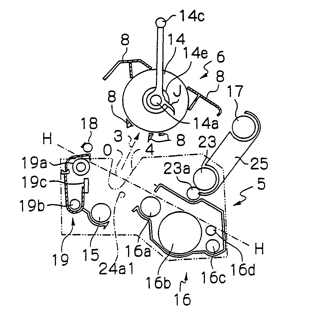
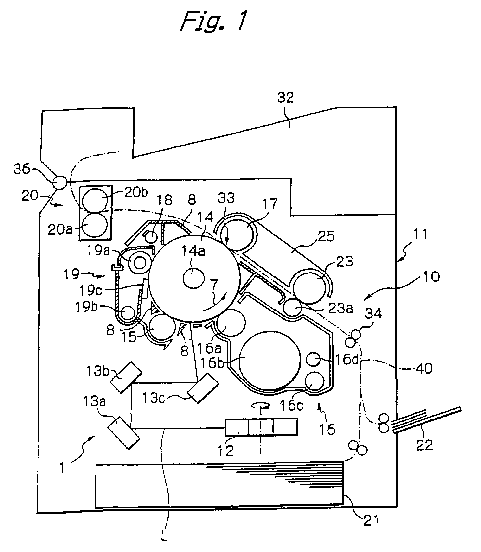
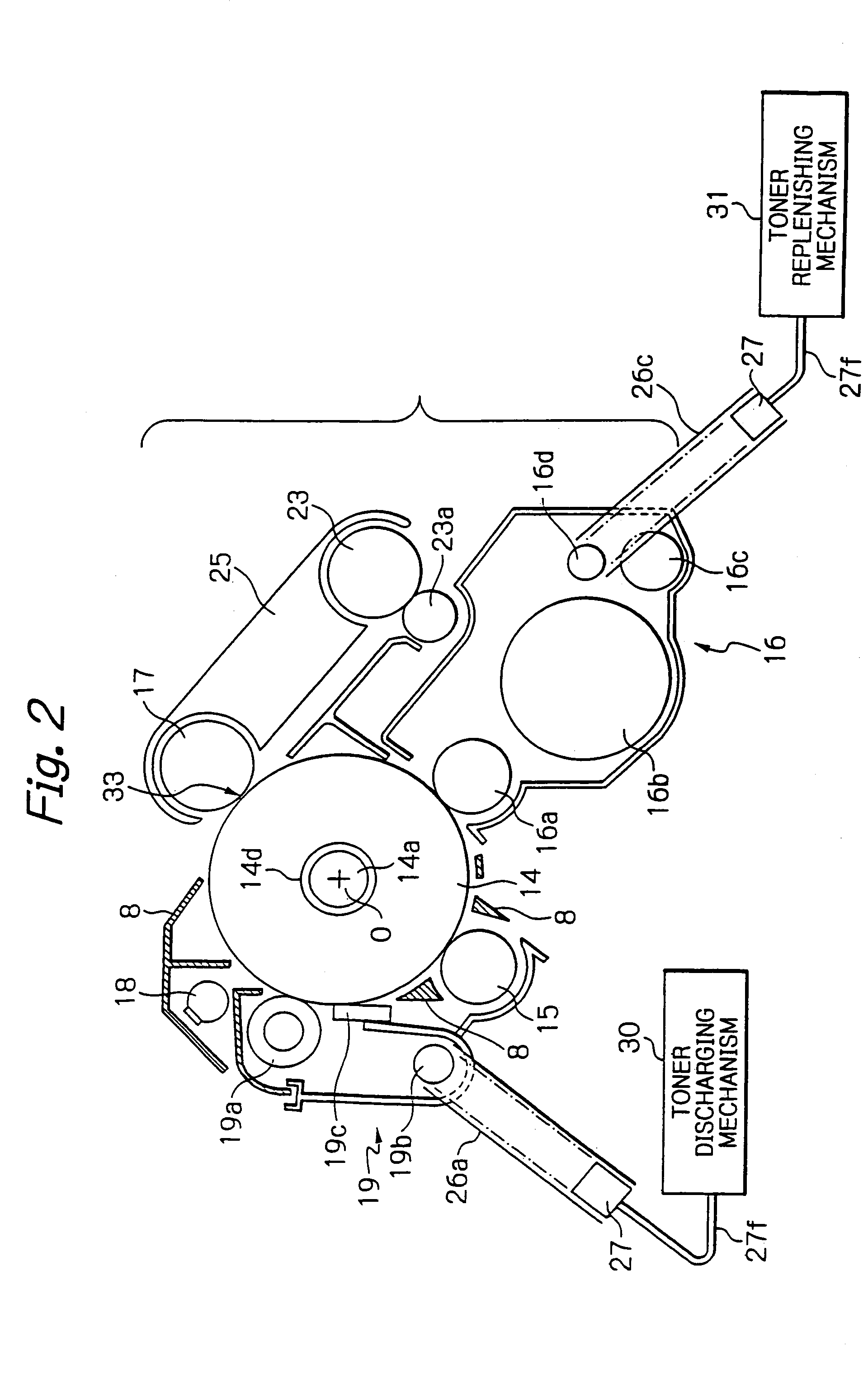
[0097]Referring to FIGS. 1 and 2, an image forming apparatus embodying the present invention is shown and implemented as a laser beam printer by way of example. As shown, the image forming apparatus, generally 11, includes an optical writing section or exposing means 1 including a light source, not shown, a polygonal mirror 12, and mirrors 13a, 13b and 13c. An image forming section 10 includes a photoconductive drum or image carrier 14, a charger or charging means 15, a developing device 16, an image transferring device 17, a quenching lamp or discharging means 18, and a cleaning device 19. A fixing device 20 includes a heat roller 20b and a press roller 20a pressed against the heat roller 20b.

[0098]A sheet tray 21 is positioned on the bottom of the apparatus 11 and loaded with a stack of paper sheets or similar recording media. The paper sheets are sequentially fed from the tray 21 one by one. A manual feed tray 22 is mounted on one side of the apparatus 11 for allowing the operat...


PUM


Abstract

An image forming apparatus of the present invention includes a plurality of components that form image forming means and should be mounted or dismounted in a preselected order. Following one of the components with respect to the preselected order cannot be dismounted from the apparatus until preceding one of the same has been dismounted. The components are mounted to the apparatus in the reverse order. The components unremovable from the apparatus and positioned above the removable components in a preselected dismounting direction are retractable.

Description

BACKGROUND OF THE INVENTION[0001]1. Field of the Invention[0002]The present invention relates to a copier, printer, facsimile apparatus or similar image forming apparatus.[0003]2. Description of the Background Art[0004]It has been customary with an image forming apparatus to entrust a serviceman with maintenance. Today, however, many ordinary users own image forming apparatuses because of the decreasing size and cost of the apparatuses. The spread of image forming apparatuses forces a single serviceman to deal with a prohibitive number of apparatuses, increasing the interval between a user's call for a serviceman and the arrival of the serviceman at the user's station. It is therefore difficult for a serviceman to maintain image forming apparatuses situated at users' stations one by one.[0005]On the other hand, the expansion of international transport means and trade has accelerated overseas production and export of image forming apparatuses. A service system relating to image formi...

Claims


Application Information

Patent Timeline
Patent Type & Authority Patents(United States)
IPC IPC(8): G03G15/00G03G15/02G03G21/16
CPCG03G21/16G03G2221/1654G03G2221/1651G03G21/1647
Inventor SAITOH, MASANORIMATSUURA, NEKKAYANAGAWA, NOBUYUKI
Owner RICOH KK
Why Eureka
Try Eureka