Method and apparatus for generating pseudo-random numbers

a pseudo-random number and method technology, applied in the field of computing systems and electronics, can solve the problems of software algorithms that are usually relatively slow and employ processes that are usually difficult to reliably implemen

Active Publication Date: 2006-07-25
ORACLE INT CORP
View PDF3 Cites 22 Cited by
  • Summary
  • Abstract
  • Description
  • Claims
  • Application Information

AI Technical Summary

Problems solved by technology

Tests for randomness are given in the NIST Special Publication 800-22 (with revisions dated May 15, 2001), titled “A Statistical Test Suite For Random And Pseudorandom Number Generators For Cryptographic Applications.” Many software algorithms for producing pseudo-random numbers pass the FIPS tests, but the software algorithms are usually relatively slow.
These hardware methods, however, employ processes that are usually difficult to reliably implement.

Method used


Image

  • Method and apparatus for generating pseudo-random numbers
  • Method and apparatus for generating pseudo-random numbers
  • Method and apparatus for generating pseudo-random numbers

Examples


exemplary embodiment 200

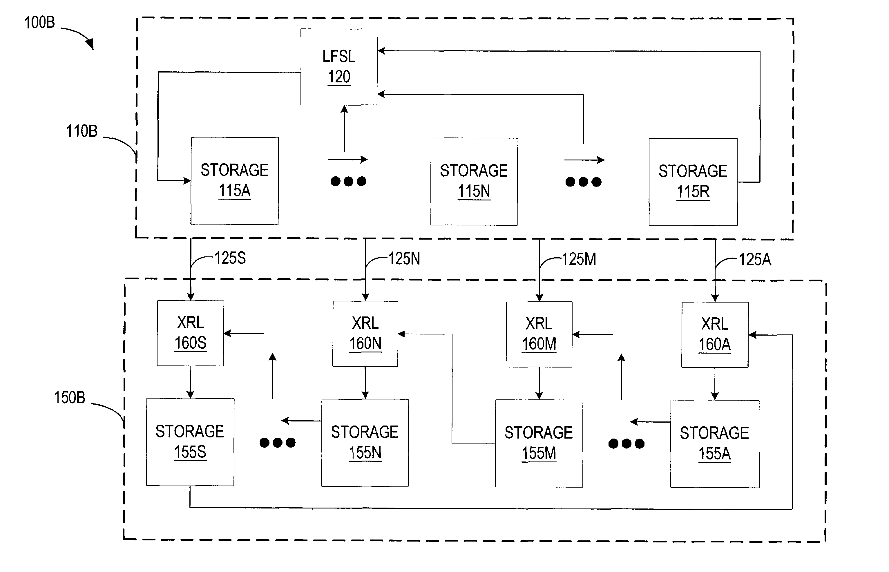
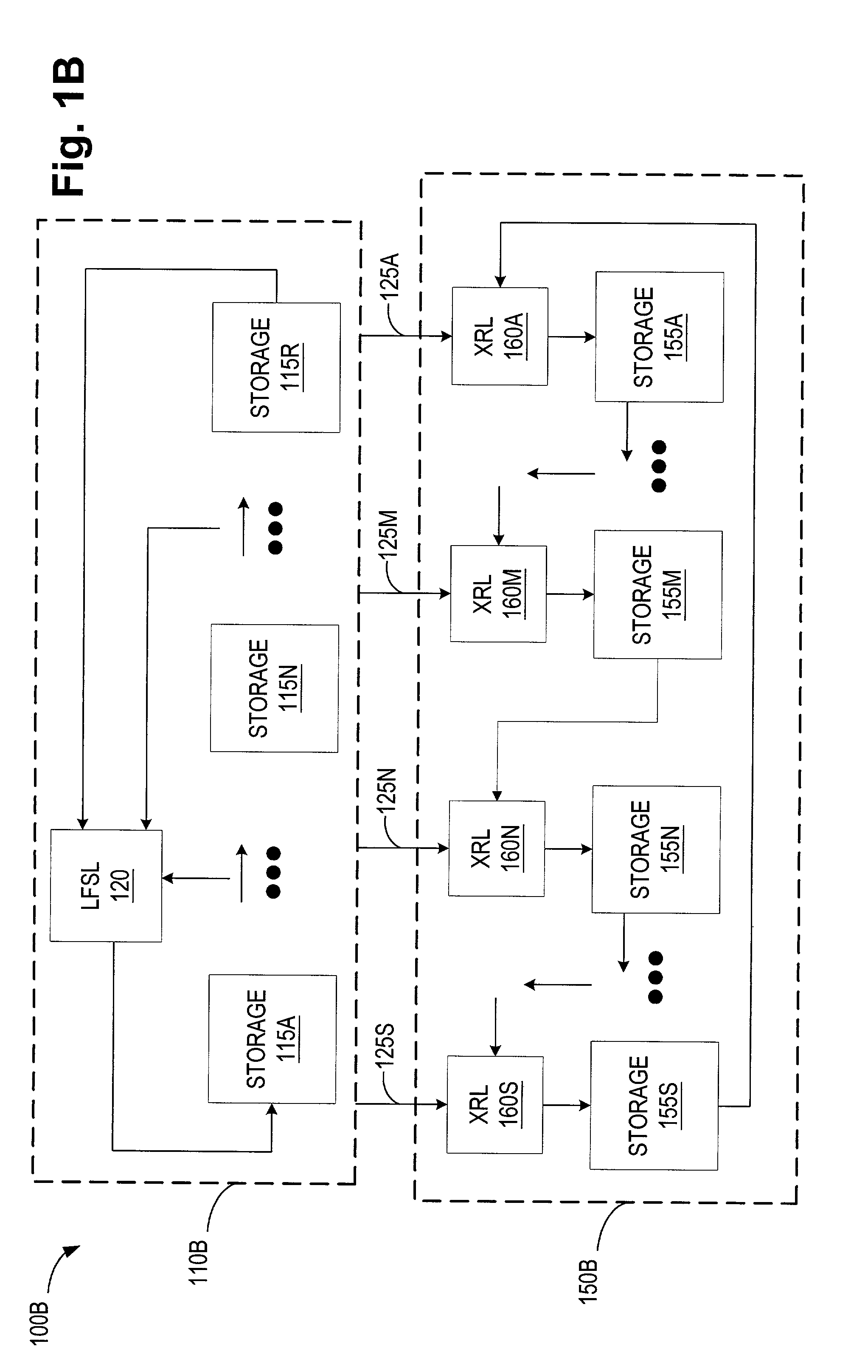
[0055]Turning to FIG. 2, a block diagram of a first exemplary embodiment 200 of the XOR pseudo-random number generator 100B of FIG. 1B, in accordance with one aspect of the present invention, is illustrated. Note that where FIGS. 1A and 1B use reference numbers in the 100s, FIG. 2 uses reference numbers in the 200s, but the tens and ones places correspond for ease of comparison.

[0056]As shown in FIG. 2, the XOR pseudo-random number generator 200 includes a linear feedback shift register 210 and an XOR register 250. The linear feedback shift register 210 provides a plurality of values 225 to the XOR register 250. Note that as shown, three potentially different values are provided as five values 225. The linear feedback shift register 210 includes three storage locations (collectively 215), labeled from left to right, and an XOR gate as a linear feedback shift logic 220. The datum stored in the storage location 215(1) is updated each iteration from the linear feedback shift logic 220 ...

exemplary embodiment 300

[0075]Turning to FIG. 3, a block diagram of a second exemplary embodiment 300 of the XOR pseudo-random number generator 100B of FIG. 1B in accordance with one aspect of the present invention is illustrated. Note that where FIGS. 1A and 1B use reference numbers in the 100s and FIG. 2 uses reference numbers in the 200s, FIG. 3 uses reference numbers in the 300s, but the tens and ones places correspond for ease of comparison.

[0076]As shown in FIG. 3, the XOR pseudo-random number generator 300 includes a linear feedback shift register 310 and an XOR register 350. The linear feedback shift register 310 provides a plurality of values 325 to the XOR register 350. Note that as shown, thirteen (13) potentially different values are provided as seventeen (17) values 225. The linear feedback shift register 310 includes 13 storage locations (collectively 315), labeled from left to right, and three XORs as linear feedback shift logic 320. For N>1, the datum stored in the storage location 315(N) i...


PUM


Abstract

A method and apparatus for generating pseudo-random numbers. The method includes defining a first set of R bits and defining a second set of S bits different from the first set of R bits. The method also includes updating the second set of S bits using a predetermined process that operates on the first set of R bits and the second set of S bits to form an updated set of S bits. The method also includes updating the first set of R bits using another predetermined process. The apparatus may include a linear feedback shift register and a second register. The linear feedback shift register is configured to store R bits. The second register is configured to store S bits. Each bit of the S bits is updated using a function that operates on one or more of the R bits from the linear feedback shift register and one or more of the S bits.

Description

BACKGROUND OF THE INVENTION[0001]1. Field of the Invention[0002]This invention relates generally to computing systems and electronics, and, more particularly, to a method and apparatus for generating pseudo-random numbers, such as in a computer system.[0003]2. Description of the Related Art[0004]The use of random numbers, both as true random numbers (TRN) and as pseudo-random numbers (PRN), has become very important in modem society. The advent of the inexpensive personal computer, with its astounding computing power for the cost, as well as more powerful server computers has led to an increased interest in computer security, data security, Monte Carlo modeling methods, and tie-breaking protocols, just to name a few of the areas where random numbers are used.[0005]U.S National Institute of Standards and Technology (NIST) cryptographic standards are specified in Federal Information Processing Standards (FIPS) Publications. Tests for randomness are given in the NIST Special Publicatio...

Claims


Application Information

Patent Timeline
Patent Type & Authority Patents(United States)
IPC IPC(8): G06F1/02H04L9/22
CPCG06F7/584H04L9/0662H04L2209/12
Inventor RARICK, LEONARD D.
Owner ORACLE INT CORP
Why Eureka
Try Eureka