Flow sleeve for a low NOx combustor

a combustible and flow sleeve technology, applied in the direction of machines/engines, mechanical equipment, light and heating equipment, etc., can solve the problems of less durable design, high operating temperature, multiple negative effects of pressure loss on hardware durability and performance, etc., to improve cooling effectiveness, improve life, and improve the effect of cooling effectiveness

Active Publication Date: 2006-08-01
H2 IP UK LTD
View PDF5 Cites 53 Cited by
  • Summary
  • Abstract
  • Description
  • Claims
  • Application Information

AI Technical Summary

Benefits of technology

[0009]A gas turbine combustor structure having improved cooling effectiveness and increased life as well as a method for improving the cooling effectiveness is disclosed. The gas turbine combustor in accordance with the preferred embodiment of the present invention comprises a generally cylindrical case that serves as a pressure vessel having a generally cylindrical end cover fixed to a first case flange. The end cover has a plurality of first fuel nozzles arranged about a center axis. Located within the case and coaxial to the center axis is a flow sleeve that is used to direct compressed air along a combustion liner for cooling and injection into the liner. The flow sleeve has a first portion that is generally cylindrical in shape, a mounting flange for mounting the flow sleeve to a second case flange, and a second portion that is generally conical in shape that is fixed to the first portion of the flow sleeve. The second portion of the flow sleeve contains a plurality of feed holes for supplying cooling air to a generally annular passageway that is formed between the flow sleeve and the combustion liner. The combustion liner is in fluid communication with a plurality of fuel nozzles and is supplied with air from the generally annular passageway for cooling of the liner walls as well as for mixing with fuel that is injected from the fuel nozzles. Hot combustion gases formed in the combustion liner are directed towards the turbine section by way of a transition duct. In order to prevent hot gases from leaking, the combustion liner seals to the transition duct by a seal located proximate the liner aft end outer wall that has a means for passing cooling air through the seal to cool beneath the seal.
[0010]The present invention avoids the shortcomings of the prior art by providing an improved flow sleeve design that reduces the pressure loss to the cooling air at the flow sleeve inlet, by approximately 50%, thereby providing the combustion liner with higher pressure air for cooling and mixing with fuel for combustion. This is accomplished by altering the flow sleeve inlet region such that all air enters the flow sleeve upstream of the transition duct and a majority of that air enters the flow sleeve through a plurality of feed holes in the conical portion of the flow sleeve. Moving the air inlet location away from the transition piece bellmouth and support ring as well as reconfiguring the inlet geometry, eliminates a majority of the pressure losses associated with the prior art configuration.
[0011]It is an object of the present invention is to provide a gas turbine combustor having lower pressure losses to the cooling air supply pressure.
[0012]It is another object of the present invention to provide a method of improving the cooling effectiveness of an aft region of a combustion liner.
[0013]It is yet another object of the present invention to provide a gas turbine combustor having improved durability as a result of the lower pressure losses to the cooling air supply.

Problems solved by technology

This disturbance to the air flow and resulting pressure loss has multiple negative effects on the hardware durability and performance.
As a result, less air is passed through the various passages requiring cooling and injected for mixing with the fuel, thereby resulting in higher operating temperatures, a less durable design, and reduced combustor performance.

Method used


Image

  • Flow sleeve for a low NOx combustor
  • Flow sleeve for a low NOx combustor
  • Flow sleeve for a low NOx combustor

Examples


Embodiment Construction

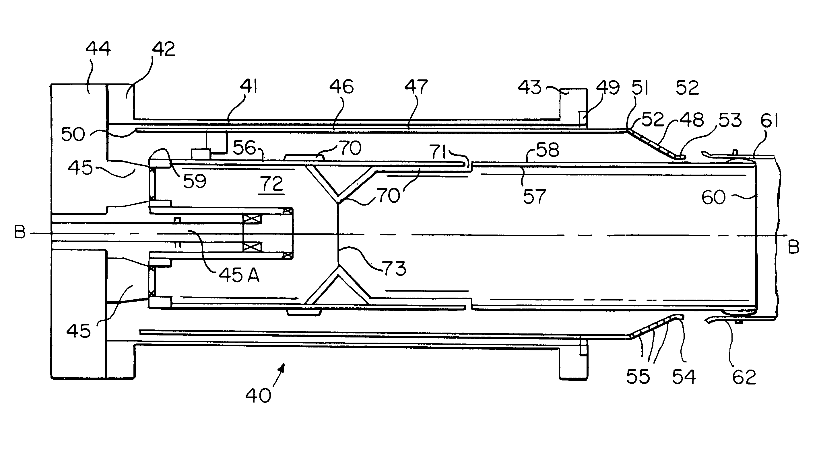
[0020]The preferred embodiment of the present invention is shown in detail in FIGS. 3–5B. Gas turbine combustor 40, in accordance with the present invention comprises a generally cylindrical case 41 having center axis B—B, first case flange 42, and second case flange 43. Fixed to first case flange 42 is a generally cylindrical end cover 44 that has a plurality of first fuel nozzles 45 arranged in an annular array about center axis B—B. Located radially within case 41 and coaxial to center axis B—B is flow sleeve 46 having first portion 47, second portion 48, and mounting flange 49. First portion 47 is generally cylindrical in shape and has a first end 50 located proximate first case flange 42. Mounting flange 49 extends radially outward from first portion 47 and is located axially along first portion 47 proximate second case flange 43, and fixes flow sleeve 46 to case 41 at second case flange 43. For the preferred embodiment, second end 51 of first portion 47 is located proximate mo...


PUM


Abstract

A gas turbine combustor structure having improved cooling effectiveness and increased life as well as a method for improving the cooling effectiveness is disclosed. The gas turbine combustor incorporates a unique flow sleeve configuration for directing air to more effectively cool a combustion liner. The flow sleeve geometry is configured to incorporate a conical aft portion having a plurality of air feed holes that reduce pressure loss to the incoming air and flow separation effects from the surrounding combustor hardware, thereby resulting in improved combustor performance.

Description

BACKGROUND OF THE INVENTION[0001]1. Field of the Invention[0002]The present invention relates to gas turbine combustors and more specifically to a flow sleeve having an inlet region that reduces pressure loss to the compressed air entering a combustor.[0003]2. Description of Related Art[0004]A gas turbine engine typically comprises a multi-stage compressor, which compresses air drawn into the engine to a higher pressure and temperature. A majority of this air passes to the combustors, which mixes the compressed heated air with fuel and contains the resulting reaction that generates the hot combustion gases. These gases then pass through a multi-stage turbine, which drives the compressor, before exiting the engine. In land-based gas turbines, the turbine is also coupled to a generator for generating electricity.[0005]For land-based gas turbine engines, often times a plurality of combustors are utilized. Each of the combustion systems include a case that serves as a pressure vessel co...

Claims


Application Information

Patent Timeline
Patent Type & Authority Patents(United States)
IPC IPC(8): F23R3/42F23R3/04F23R3/34
CPCF23R3/04F23R3/34F23R2900/03042
Inventor MARTLING, VINCENT C.SPALDING, MARTIN JOHNPOYYAPAKKAM, MADHAVAN
Owner H2 IP UK LTD
Why Eureka
Try Eureka