Air conditioning apparatus for vehicle

Inactive Publication Date: 2006-08-01
DENSO CORP
View PDF14 Cites 25 Cited by
  • Summary
  • Abstract
  • Description
  • Claims
  • Application Information

AI Technical Summary

Benefits of technology

[0019]In this way, by intermitting the refrigerant flowing into the cooling heat exchanger, the cooling temperature of the cooling heat exchanger can be maintained at the set temperature so that the frosting of the cooling heat exchanger is prevented. At that time, since the set temperature is set to be higher according to the decrease in a temperature of the outside air, it is certainly possible to prevent a frosting of a part at the outside-air passage side, of the cooling heat exchanger in winter season, which is caused by the low-temperature outside air flowing into the outside air passage.
[0020]That is, since the temperature sensor is disposed in the first air passage, i.e., the inside-air passage, when the inside air/outside air double laminar mode is

Problems solved by technology

As a result, it turns out that the following problem occurs.
However, if the set temperature of the temperature sensor 39 is set to be higher as described above, in winter season where the outside-air temperature is

Method used


Image

  • Air conditioning apparatus for vehicle
  • Air conditioning apparatus for vehicle
  • Air conditioning apparatus for vehicle

Examples


first embodiment

[0038]the present invention will be described.

[0039]In this embodiment, each of air conditioning components in an air conditioning unit for air conditioning a space in a passenger compartment of a vehicle having a diesel engine mounted thereon is controlled by an air conditioning control apparatus (hereinafter referred to as “ECU”.

[0040]Firstly, a construction of the air conditioning unit will be described with reference to FIG. 1.

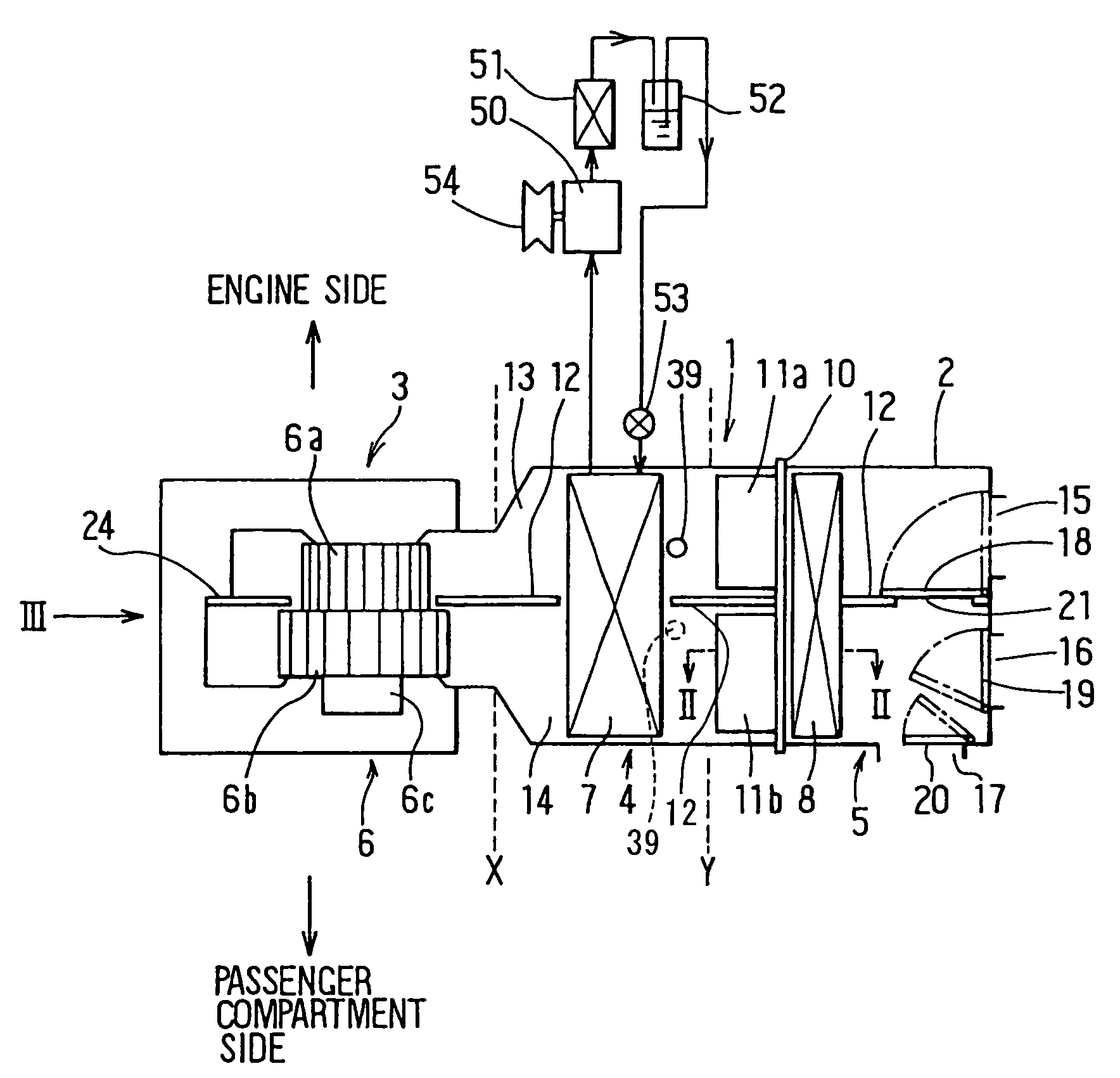
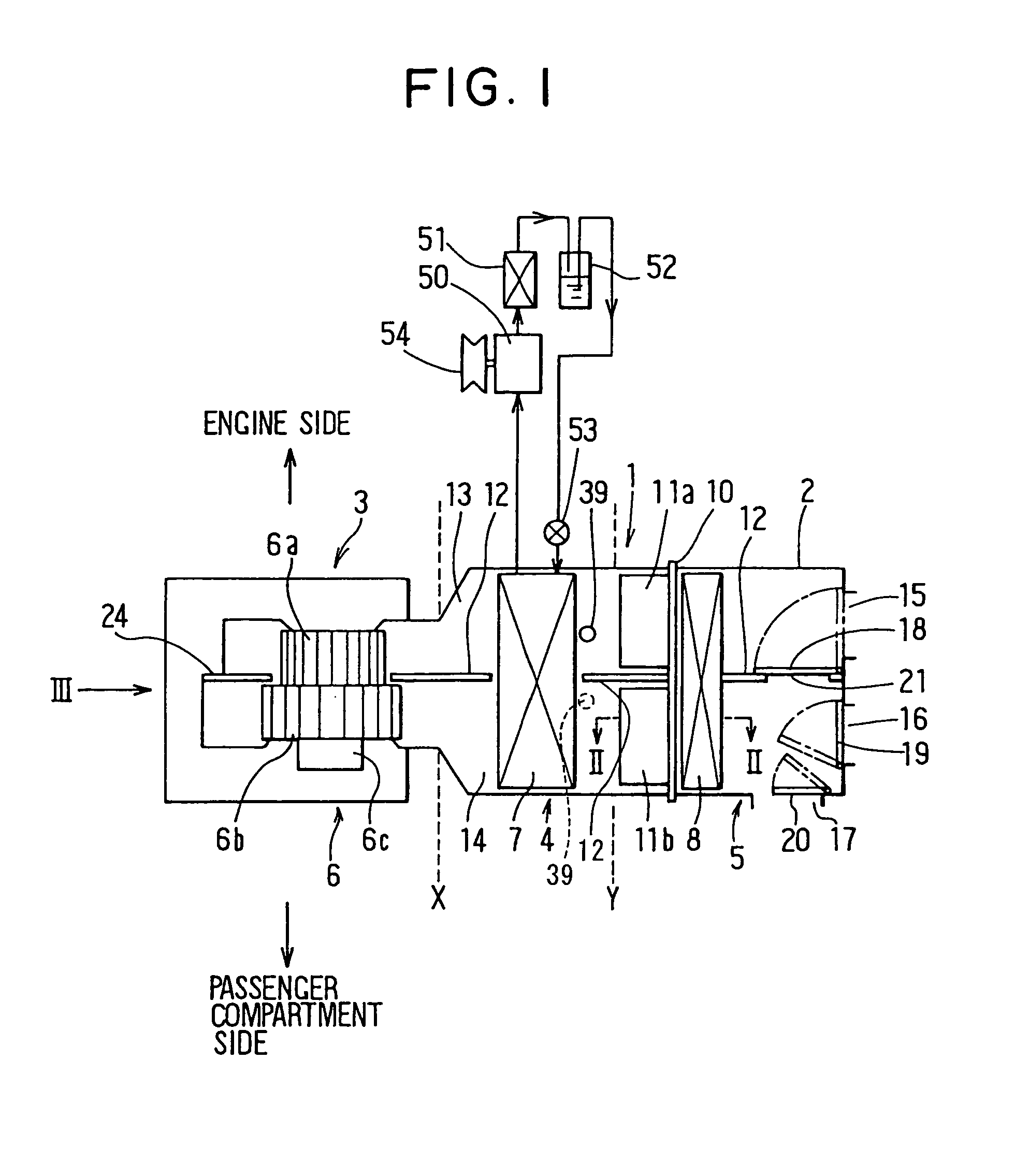
[0041]The air conditioning unit 1 is mounted on the vehicle in such a manner that an upward direction of FIG. 1 is set to a front direction of the vehicle (toward the engine), a downward direction of FIG. 1 is set to a rear direction of the vehicle (toward the passenger compartment), and a right-and-left direction of FIG. 1 is set to a width direction of the vehicle. The air conditioning unit 1 is provided with an air conditioning case 2 for forming an air passage for introducing conditioned air into the passenger compartment.

[0042]The air conditioning cas...

second embodiment

[0100]the present invention will be described.

[0101]The second embodiment differs from the first embodiment in that the post-evaporator temperature sensor 39 is disposed in the second air passage 14 as shown in phantom in FIG. 1 of step 180a in FIG. 6 is modified. The other features are same as in the first embodiment.

[0102]As described above with reference to FIGS. 11C and 11D, when the post-evaporator temperature sensor 39 is disposed in the second air passage 14 of the evaporator 7, the temperature of air blown out from a part at the inside-air of the evaporator 7 increases so that the dehumidifying capacity may be deteriorated. In the second embodiment, as shown at step 180a′ of FIG. 10, in winter season where the outside-air temperature Tam is low, the set temperatures T1 and T2 are set in a low area A (e.g., T1=2° C., T2=3° C.). In an intermediate period of spring or fall, the set temperatures T1 and T2 are set in an intermediate area B (e.g., T1=3° C., T2=4° C.). In summer se...

fourth embodiment

[0137]the present invention will be described.


PUM


Abstract

An interior of an air conditioning case is partitioned into a first air passage extending from an inside air suction port to a foot opening portion and a second air passage extending from an outside air suction port is disposed at a side of the first air passage to detect a temperature of air blown out from the evaporator disposed in the first air passage and the second air passage. An operation of the compressor for supplying the refrigerant to the evaporator is intermitted by comparing the temperature detected by the temperature sensor and the set temperature set in advance, and the set temperature is changed to be higher according to an increase in the temperature of outside air. In this way, it is possible to prevent the frosting of the evaporator in winter season, when the inside air is introduced into the first air passage and the outside air is introduced into the second air passage.

Description

CROSS REFERENCE TO THE RELATED APPLICATIONS[0001]This application is a continuation-in-part of U.S. application Ser. No. 08 / 872,647 filed on Jun. 10, 1997 now abandoned and claims priority of Japanese Patent Application No. Hei. 8-273715 filed on Oct. 16, 1996. The application is also related to Japanese Patent Applications Nos. Hei. 8-152721 filed on Jun. 13, 1996, Hei. 8-340107 filed on Dec. 19, 1996, and Hei. 8-340182 filed on Dec. 19, 1996.BACKGROUND OF THE INVENTION[0002]1. Field of the Invention[0003]This invention relates to an air conditioning apparatus having a first air passage and a second air passage, formed in an air conditioning case, in which inside air and outside air are introduced into the first air passage and the second air passage, respectively.[0004]2. Description of Related Art[0005]In a conventional air conditioning apparatus as disclosed in JP-A-5-124426, there are formed at one end side of an air conditioning case an inside-air inlet for introducing inside ...

Claims


Application Information

Patent Timeline
IPC IPC(8): F25B29/00B60H1/32B60H3/00
CPCB60H1/00849B60H1/321B60H2001/3283B60H2001/327B60H2001/3261
Inventor UEMURA, YUKIOSUWA, KENJISHIKATA, KAZUSHI
Owner DENSO CORP
Why Eureka
Try Eureka