Rod or piston primary seal

a technology of primary seals and rods, applied in the direction of sealing, braking systems, machines/engines, etc., can solve the problems of delayed time, no longer present sufficient sealing function, early failure of sealing arrangements, etc., to achieve broad applications, counteract pressure build-up, and simple design

Inactive Publication Date: 2006-08-01
CARL FREUDENBERG KG
View PDF20 Cites 20 Cited by
  • Summary
  • Abstract
  • Description
  • Claims
  • Application Information

AI Technical Summary

Benefits of technology

[0007]It is an object of the invention to create a sealing arrangement which is simple in design and which counteracts a pressure build-up in the sealing space between two individual seals. In the case of a pressure drop on the high-pressure side, a pressure build-up in the sealing space should not be clamped in at a higher pressure level or rather may follow the pressure drop on the high-pressure side only greatly delayed in time. At the same time, when there is a renewed pressure increase on the high-pressure side, none or only a small pressure increase should take place in the sealing intermediate space.
[0008]These and other objects of the invention are achieved by a rod or piston primary seal, using a primary seal facing space (1) to be sealed and a secondary seal facing away from it, in which the primary seal is fitted into an open groove in a holding element open in the direction of the relatively movable machine part which is bounded, on the side facing away from the space to be sealed, by a first side surface which extends essentially at right angles to the sealing axis, and includes a sealing edge ring made of tough plastic which has a sealing edge lying against the machine...

Problems solved by technology

This may cause inadmissible deformations to appear on the sealing edge ring, which may result in leakage or early failure of the sealing arrangement.
Pressure reversal occurs particularly when a pressure drop takes place on the high-pressure side, and the pressure build-up in the sealing space between the prim...

Method used


Image

  • Rod or piston primary seal
  • Rod or piston primary seal
  • Rod or piston primary seal

Examples


Embodiment Construction

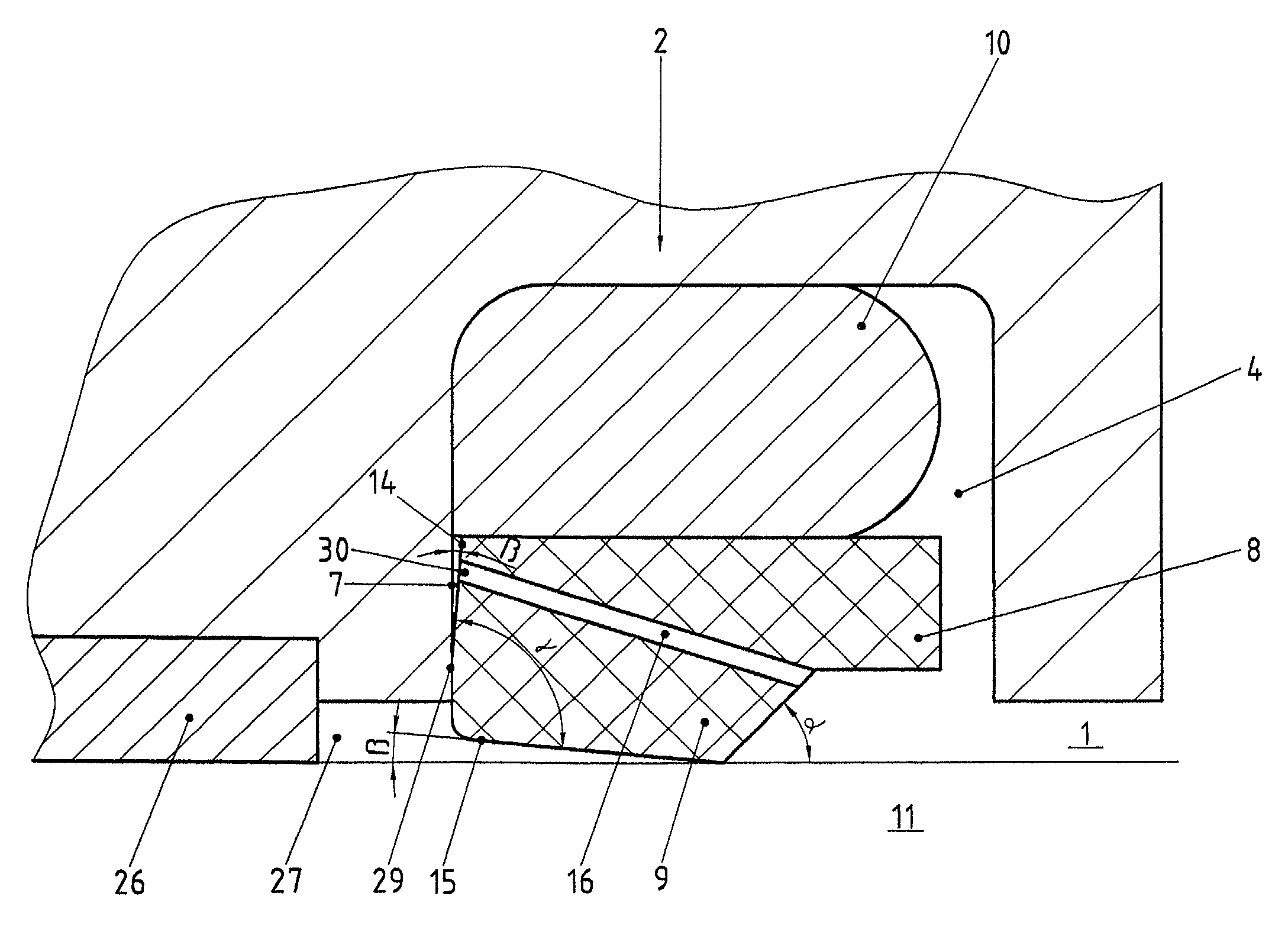
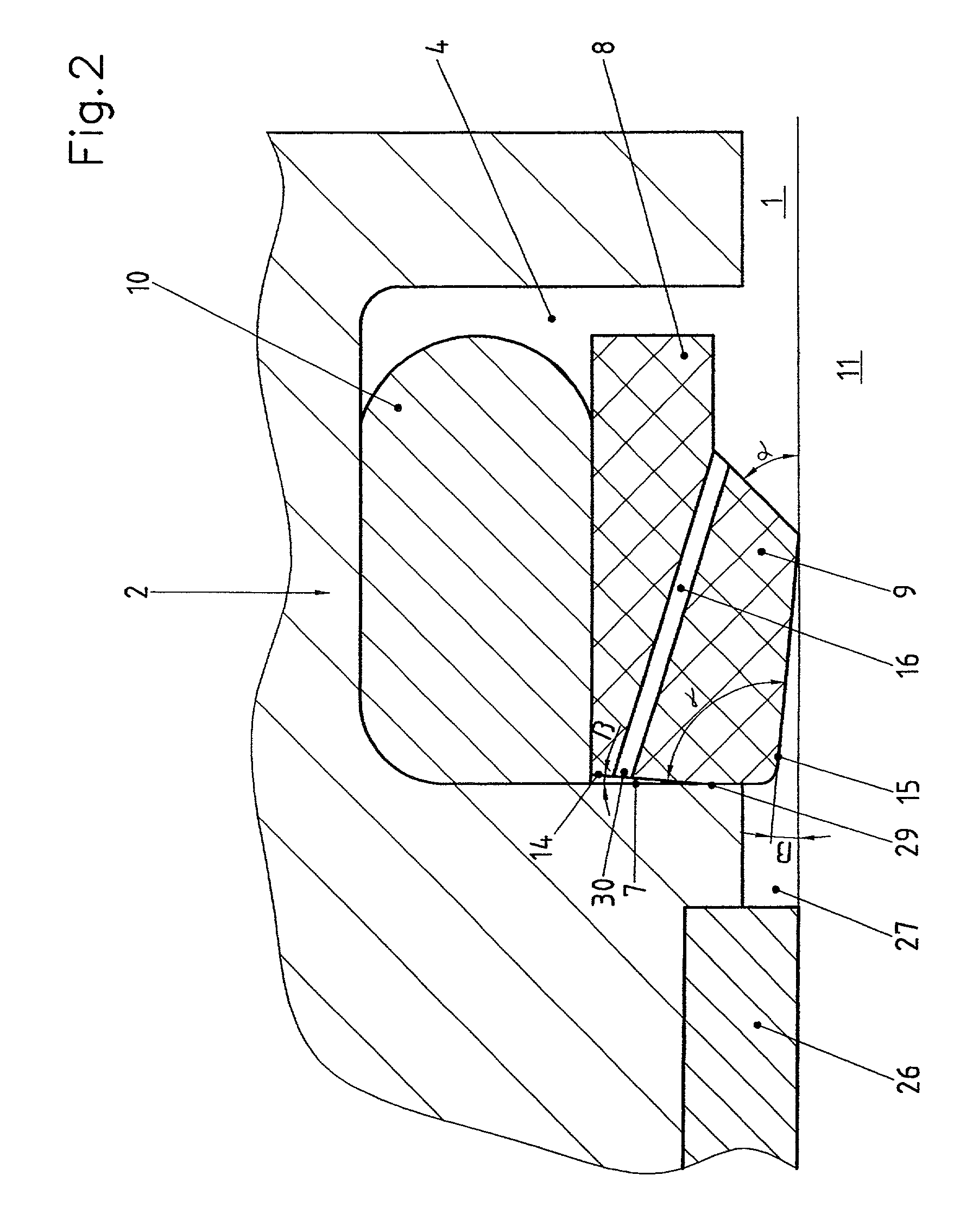
[0013]In order to achieve great functional reliability, it is possible to provide the sealing edge ring, on the side of the sealing edge facing the space to be sealed, with a peripheral support protuberance, and to ventilate the space between the sealing edge and the support protuberance by at least one axial groove in the support protuberance. During its production, the support protuberance is developed so that its nominal diameter essentially matches that of the sealing edge.

[0014]In order to achieve an axial orientation between sealing edge ring and profile ring, the sealing edge ring can grip from behind the profile ring on the side facing away from the space to be sealed, using a first projection. In addition, the press-on ring can be supported by a side protuberance on the side surface of the groove facing the space to be sealed.

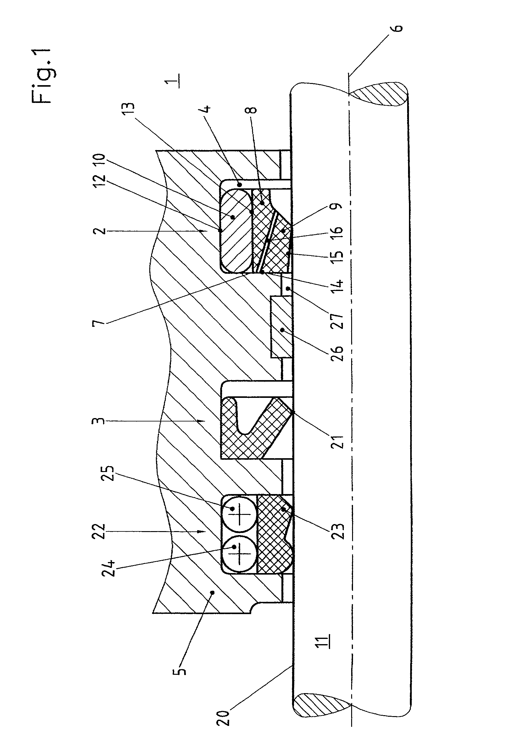
[0015]FIG. 1 shows a holding element 5 in cross section, for example, a housing wall, through which machine part 11 passes. On the right side of holdi...


PUM


Abstract

A rod or piston primary seal, which includes a primary seal (2) facing the space (1) to be sealed and a secondary seal (3) facing away from it, in which the primary seal (2) is fitted into the groove (4), of a holding element (5), open in the direction of the relatively movable machine part (11) which is bounded, on the side facing away from the space (1) to be sealed, by a first side surface (7) which extends essentially at right angles to the sealing axis (6), and includes a sealing edge ring (8) made of tough, hard plastic which has a sealing edge (9) lying adjacent to the machine part (11) and is pressed with its sealing edge (9) onto the machine part (11) by a profile ring (10) made of elastomeric material which is supported on the bottom surface (12) of groove (4) and lies adjacent to sealing edge ring (8) with its inner surface (13), the sealing edge ring (8) having a profile bounded essentially by a right angle between the sealing edge (9) and the bounding surface (14) facing the first side surface (7); and, in the unloaded state of seal (2), surface (15) bounding the sealing edge (9) on the side facing away from the pressure subtends an angle (β) of at most 8° with the sealing axis (6); and the sealing edge ring (8) is penetrated by at least one discharge opening (16) positioned between sealing edge (9) and the outer surface of wiper ring (8) and opens out onto the bounding surface (14).

Description

BACKGROUND OF THE INVENTION[0001]1. Field of the Invention[0002]The invention relates to sealing arrangements which are used for sealing axially movable rods or pistons, in order to seal a high-pressure side from a low-pressure side.[0003]2. Description of Related Art[0004]For these seals, frequently sealing edge rings are used, which are made of tough, elastic plastic based on PTFE or a harder thermoplastic which have one or more sealing edges at their inner circumferential surface. On their outer side, the sealing edge rings have a profile ring made of a softer elastomer material additionally pressed on radially and sealed. Sealing edge ring and profile ring are installed in a housing groove. When several seals are arranged one after another on a rod, in the case of translatory motion of the two machine parts to each other, an inverted pressure situation can occur, whereby the pressure difference reverses itself, that is, the low-pressure side becomes the high-pressure side, and t...

Claims


Application Information

Patent Timeline
IPC IPC(8): F16J15/16F15B15/12F16J15/18F16J15/3208F16J15/56
CPCF16J15/164F16J15/56F16J15/3208Y10S277/926
Inventor BORSTEL, DIETER VONREICHOW, GUNTERTIMMERMANN, HANS-JURGEN
Owner CARL FREUDENBERG KG
Why Eureka
Try Eureka