Writing implement

a technology of writing implements and writing pens, which is applied in the direction of ink reservoir pens, brushes, printing, etc., can solve the problems of inability to advance and retreat, ink leakage, and little practicality

Inactive Publication Date: 2006-08-01
MITSUBISHI PENCIL CO LTD
View PDF12 Cites 4 Cited by
  • Summary
  • Abstract
  • Description
  • Claims
  • Application Information

AI Technical Summary

Benefits of technology

[0066]Although the pressure in the storing part of the liquid for ink may increase and decrease due to an outside temperature or heat transmission in use, leakage of the liquid for ink caused by the increase and decrease thereof can be prevented by using the pressure-regulating part which controls the increase and decrease of the pressure.

Problems solved by technology

However, the figure is so incomplete that it is presumed that the advance and retreat is impossible.
Even if the advance and retreat is possible, the advance and retreat of the arrow-headed water-stopper cannot prevent water infiltration resulting in ink leakage and has little practicality.
Moreover, since the fountain pen described in the document stores solid ink which is to be mixed with water being separately stored, it is not a writing implement having a specific appearance.

Method used


Image

  • Writing implement
  • Writing implement
  • Writing implement

Examples


first embodiment

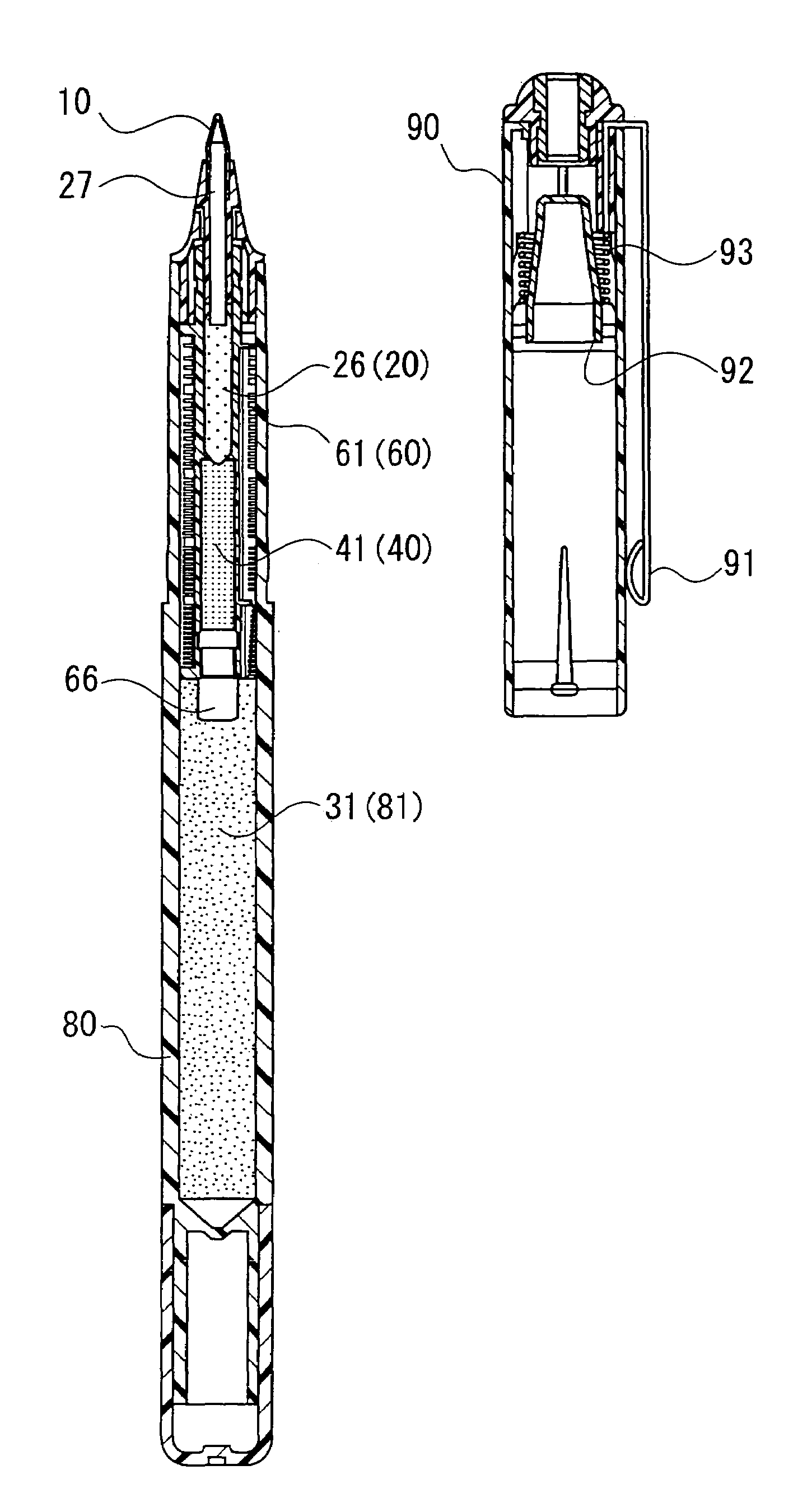
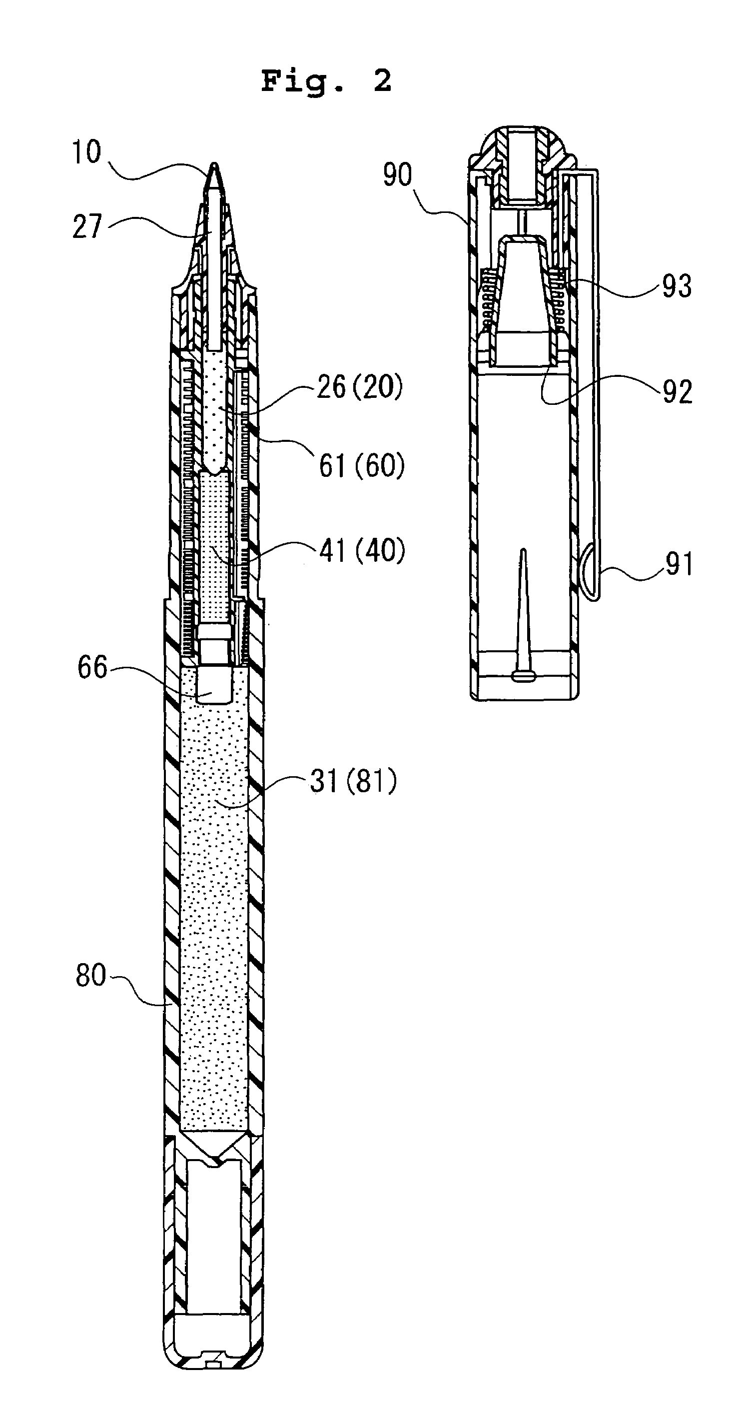
[0096]Next, the first embodiment will be described with reference to FIGS. 2 to 4. The embodiment corresponds to the type “g” illustrated in FIG. 1.

[0097]The writing implement comprises a cylindrical shaft member 80 and a pen tip member 10 provided in front of the member 80 (above the member 80, in FIG. 2), and also comprises a liquid-storing part 81 for storing liquid for ink 31 in an interior of a rear side of the shaft member 80. The liquid-storing part 81 is wholly made of synthetic resin such as polypropylene (PP) in order to show a colorless and transparent appearance so that an internal structure can be visually recognized. The shaft member 80 may not always be formed in a cylindrical shape, but its periphery may be formed in a polygonal shape.

[0098]Moreover, the shaft member 80 may not always be formed to be colorless and transparent, but may be formed to be colored and transparent, or translucent, for example. Further, the whole shaft member 80 may not always be formed to b...

second embodiment

[0130]FIGS. 5 and 6 illustrate the second embodiment. The present embodiment corresponds to a type “c” in FIG. 1.

[0131]A difference between the present embodiment and the first one is a shape of colorant-adding core 26. That is, whereas, in the first one, the contacting portions with the ink-introducing core 27 and with the colorant-adsorbing core 41 are tapered to reduce their diameters relative to other portions in order to narrow the contacting portions, every portion has the same diameter in the present one. Although the object of the first one is to appropriately supply the liquid for ink 31 and to restrict a back flow of the colorant 20, the object of the second one is to smoothly supply the liquid for ink 31.

third embodiment

[0132]FIGS. 7 and 8 illustrate the third embodiment. The present embodiment corresponds to a type “g” in FIG. 1.

[0133]A difference between the present embodiment and the first one is also a shape of colorant-adding core 26. That is, the contacting portions with the ink-introducing core 27 and with the colorant-adsorbing core 41 function as the flow rate restriction part 26a (a throttle part) which is formed by reducing its diameter. Further, a flow rate restriction member 29 made of a cylindrical elastic body is plugged over the flow rate restriction part 26a. Consequently, as well as the first one, the liquid for ink 31 can be appropriately supplied and a back flow of the colorant 20 can also be restricted. Thus, the color and its thickness can be stably maintained for a long time.

[0134]As for the elastic flow rate restriction member 29, material through which the liquid for ink 31 cannot permeate such as synthetic resin, for example, is used.


PUM


Abstract

A writing implement includes a cylindrical shaft member, a pen tip member which is fixed to one end of the shaft member and from which colored ink seeps out, liquid for ink which is stored in the shaft member and which comprises a part of the colored ink seeping out from the end of the pen tip member, and colorant to be added to the above described liquid for ink to be the colored ink. Moreover, at least a part of a cylindrical side surface of the shaft member corresponding to the storing part of the liquid for ink is formed to be transparent. Between the liquid for ink and the colorant-storing part storing the colorant is provided a colorant-adsorbing core which introduces the liquid for ink into the colorant-storing part while capturing the colorant diffusing toward the storing part of the liquid for ink.

Description

TECHNICAL FIELD[0001]The present invention belongs to a field related to manufacture of a writing implement which uses ink. The writing implement stores liquid for ink and colorant separately therein, both of which are to be included in the ink, whereby the colorant is added to the liquid for ink in process of introducing the liquid for ink to a tip member of the pen in order to produce colored ink, thereby allowing for writing in the colored ink.BACKGROUND ARTPrior Art[0002]A writing implement, which stores colored ink therein and introduces the ink to a tip of the writing implement in order to write down, specifically includes a fountain pen, a ballpoint pen, a felt pen, a sign pen (a marking pen), or a needle pen, for example. In the case of the ink which is used for such a writing implement, dye or pigment is dissolved or dispersed in vehicle matter (solvent or medium) substantially uniformly in advance, and the ink is so prepared that its color shown when contained in the writi...

Claims


Application Information

Patent Timeline
Patent Type & Authority Patents(United States)
IPC IPC(8): B43K5/02A46B11/06B43K7/00A46B11/04B43K5/00B43K5/18B43K7/10B43K8/04
CPCB43K5/005B43K8/04B43K7/10B43K5/18
Inventor IIDA, HISASHIOKUMURA, SHIGERUMATSUMOTO, KAZUAKIKOBAYASHI, SEIICHIKOBAYASHI, YUSUKE
Owner MITSUBISHI PENCIL CO LTD
Why Eureka
Try Eureka