Clean room facility and construction method

a technology for cleaning rooms and construction methods, applied in lighting and heating apparatus, ventilation systems, heating types, etc., can solve the problems of large equipment cost, high cost, and insufficient support of equipment on the raised floor, so as to reduce the transmission of vibrations and expand the area of the clean room

Inactive Publication Date: 2006-08-01
NOVELLUS SYSTEMS
View PDF44 Cites 35 Cited by
  • Summary
  • Abstract
  • Description
  • Claims
  • Application Information

AI Technical Summary

Benefits of technology

[0015]In accordance with one embodiment of the invention, a clean room is provided having a bearing floor capable of supporting equipment in any location thereon. The bearing floor is positioned over a facilities room which, in effect, is an extension of the clean room. The bearing floor has a regular array of openings through the floor which permit air to flow from the clean room into the underlying facilities room. A wall structure is positioned on the bearing floor to surround a selected area of the bearing floor. A ceiling having a plurality of filtered air inlets is provided above the bearing floor and in contact with the top of the wall structure. A plurality of grates are positioned in those floor openings of the regular array that are located within the selected area bounded by the walls and solid, air impervious members are positioned in those floor openings of the regular array that are located outside the selected area. By substituting air impervious members for grates, or vice versa, the area of the clean room can be expanded or reduced. Preferably the location and number of filtered air inlets is also adjusted to correspond to the number of grated openings in the clean room floor.
[0016]In accordance with the further aspect of the invention, a floor configuration is provided which significantly reduces the transmission of vibrations to, from, and among vibration-sensitive equipment disposed on the floor. Indeed, although the vibration dampening floor configurations of the present invention are disclosed herein in the context of a clean room, such floor configurations may be utilized in any environment where vibration isolation is desired.

Problems solved by technology

The raised floor itself is usually inadequate to support the weight of the equipment.
The necessary pedestal structures are often very expensive, sometimes having a cost equaling a large percentage of the total equipment cost.
In addition to the expense of the customized pedestals used to support a raised clean room floor, there are a number of other significant drawbacks to a raised floor configuration.
Because the raised floor, by itself, is unable to support the weight of equipment that might be placed in the clean room, the raised floor also cannot support the weight of that equipment as it is being moved within the clean room.
This results in the necessity for disassembling the raised floor when equipment is moved into a clean room or is moved about the clean room.
This activity compromises the cleanliness of the clean room every time a piece of equipment is moved into, out of, or about the clean room.
In addition, any facilities lines that may be located under the portion of the raised floor that is removed will also be disturbed by the moving of equipment.
Because of these difficulties, it is commonplace to build relatively small or compartmentalized clean rooms so that only a small area is contaminated by any moving process.
This, of course, leads to disadvantages in terms of material flow because materials being processed must be moved into and out of these individual compartmentalized clean rooms.
Although the raised floor and the platform upon which the raised floor is supported may dampen vibrations propagated by the underlying structural floor, the underlying slab floors found in known clean rooms nonetheless tend to be a conduit for vibration.
The problem of vibration isolation is complicated by the fact that it is often difficult to identify with certainty and to prioritize the factors that impart vibration to vibration-sensitive equipment.

Method used


Image

  • Clean room facility and construction method
  • Clean room facility and construction method
  • Clean room facility and construction method

Examples


Embodiment Construction

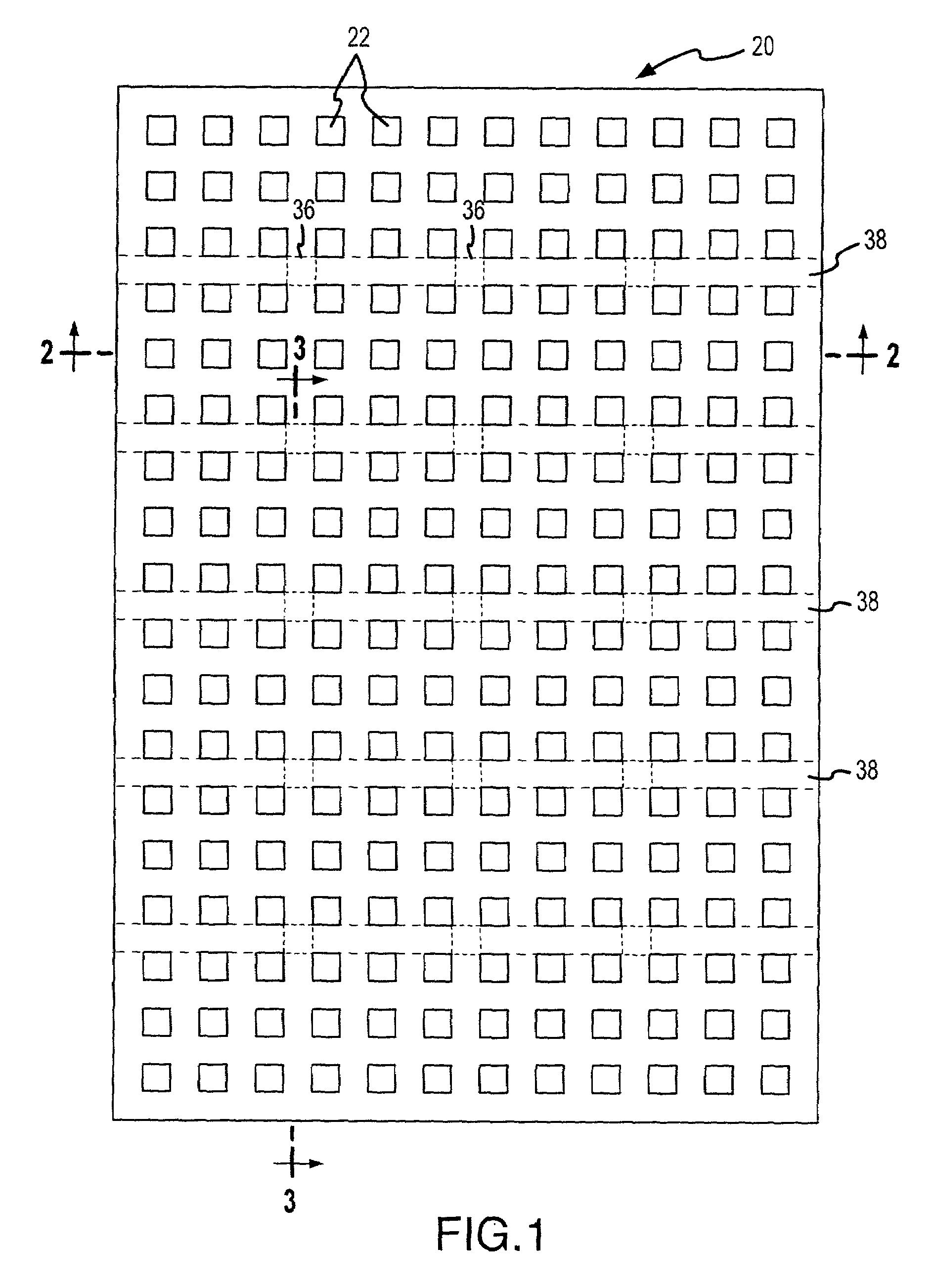
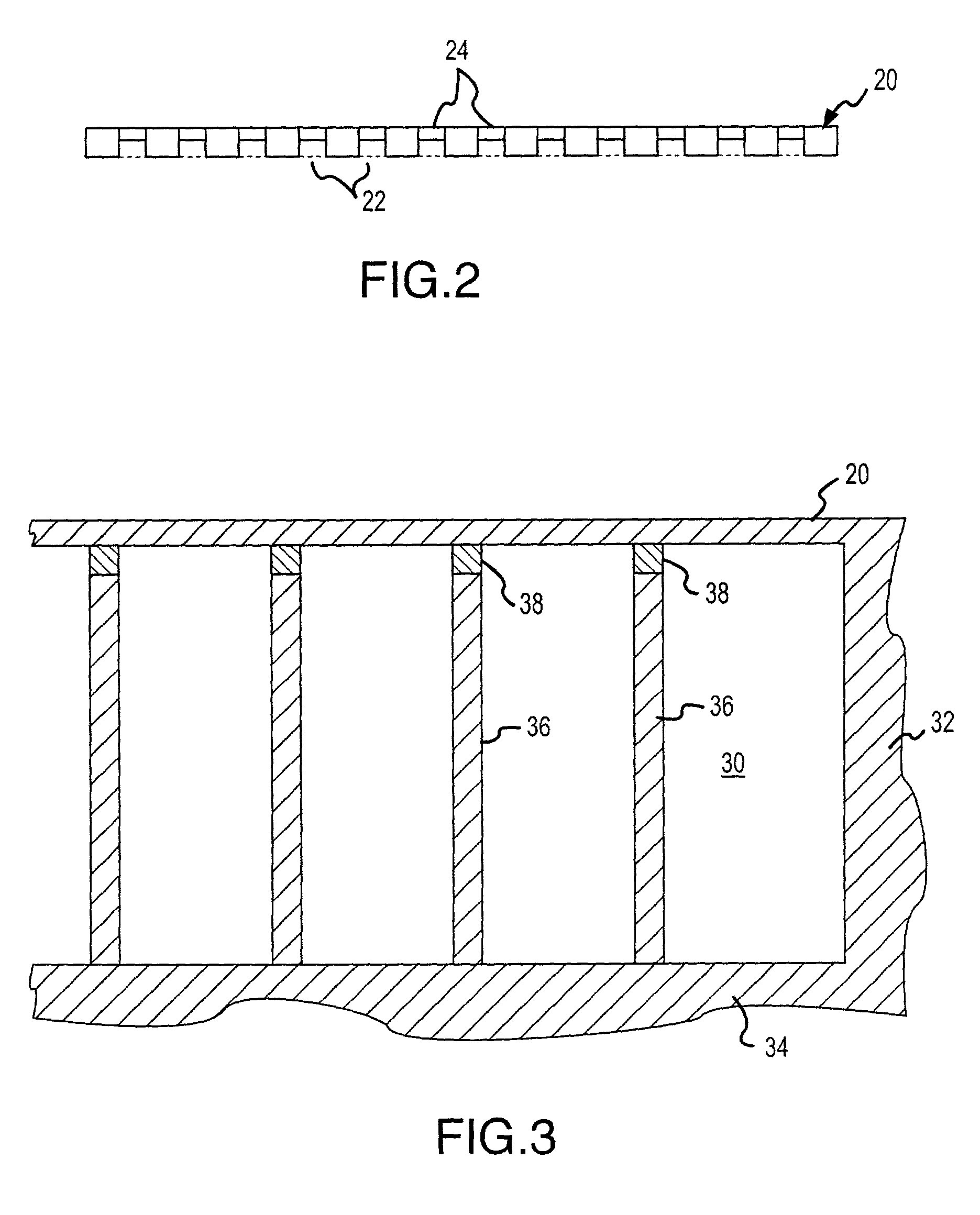
[0037]FIG. 1 illustrates, in plan view, a floor 20 for a clean room in accordance with one embodiment of the invention. FIG. 2 illustrates a cross-section taken through the floor 20, as indicated, and FIG. 3 illustrates a further cross-section through floor 20 and the substructure, as indicated.

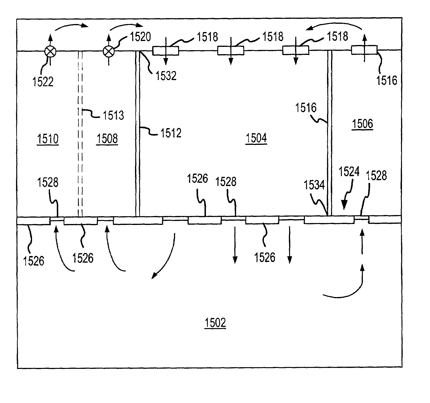
[0038]In accordance with one embodiment of the invention, as illustrated in FIGS. 1–3, the floor 20 is a poured-in-place concrete floor having a plurality of openings 22 extending through the thickness of the floor. The plurality of openings 22 are preferably arranged in a regular array. The openings can be, for example, square openings, rectangular openings, circles, ovals, ellipsis, triangles, trapezoids, parallelograms, random shapes, a combination thereof, or any other convenient form. In the context of the present invention, the openings serve a number of different functions, including one or more of the following: (i) providing a path for airflow from the clean room into an air plenum t...


PUM


Abstract

A vibration-inhibiting flooring structure for use in a facility housing vibration sensitive equipment includes a perforated bearing floor which includes a number of openings configured to inhibit the propagation of vibrations across the floor. Such a flooring structure may be used, for example, in connection with advanced clean-room facilities, where a facilities room and one or more plenums are provided in conjunction with the vibration-inhibiting floor.

Description

CROSS-REFERENCE TO RELATED APPLICATIONS[0001]This is a continuation-in-part of U.S. application Ser. No. 09 / 391,113, filed Sep. 7, 1999 now U.S. Pat. No. 6,574,937.BACKGROUND OF THE INVENTION[0002]This invention relates generally to an improved clean room facility and to a novel method for constructing the clean room facility, and more specifically to an improved floor configuration for a clean room.[0003]Clean rooms are used extensively in the electronics industry and in other industries in which a clean, substantially particle free environment is necessary during the design, fabrication, assembly, or testing of a product. Clean rooms are rated by the number of particles of a given standard size that are detected in a standard volume within the clean room. According to this rating system a “Class 10” clean room has only one-tenth the particle count of a “Class 100” clean room. Similarly, a “Class 1” clean room has only one-tenth the particle count of a “Class 10” clean room. The lo...

Claims


Application Information

Patent Timeline
Patent Type & Authority Patents(United States)
IPC IPC(8): E04B5/43E04H5/02E04H9/02F24F13/08F24F7/00E04B1/98E04B5/48E04B9/02E04F15/02E04F15/024F24F3/16F24F7/06F24F7/10
CPCE04B1/98E04B5/43E04B5/48E04B9/02E04F15/02405E04F15/02458F24F3/161F24F7/10E04F15/024F24F2221/40F24F3/167
Inventor RAPISARDA, JOSEPH R.COLLEY, TIMOTHY
Owner NOVELLUS SYSTEMS
Why Eureka
Try Eureka