
Wind energy unit comprising a hollow shaft for rotor hub and generator

a hollow shaft and generator technology, applied in the direction of wind acting propulsive elements, electrical apparatus, propulsive elements, etc., can solve the problems of reducing the efficiency of the generator, and requiring a larger air gap to be set, so as to achieve the effect of reducing the weight of the generator, enhancing the operation reliability of the generator, and reducing the moment loading on the bearing

Inactive Publication Date: 2006-08-01
WOBBEN ALOYS
View PDF21 Cites 39 Cited by
  • Summary
  • Abstract
  • Description
  • Claims
  • Application Information

AI Technical Summary

Benefits of technology

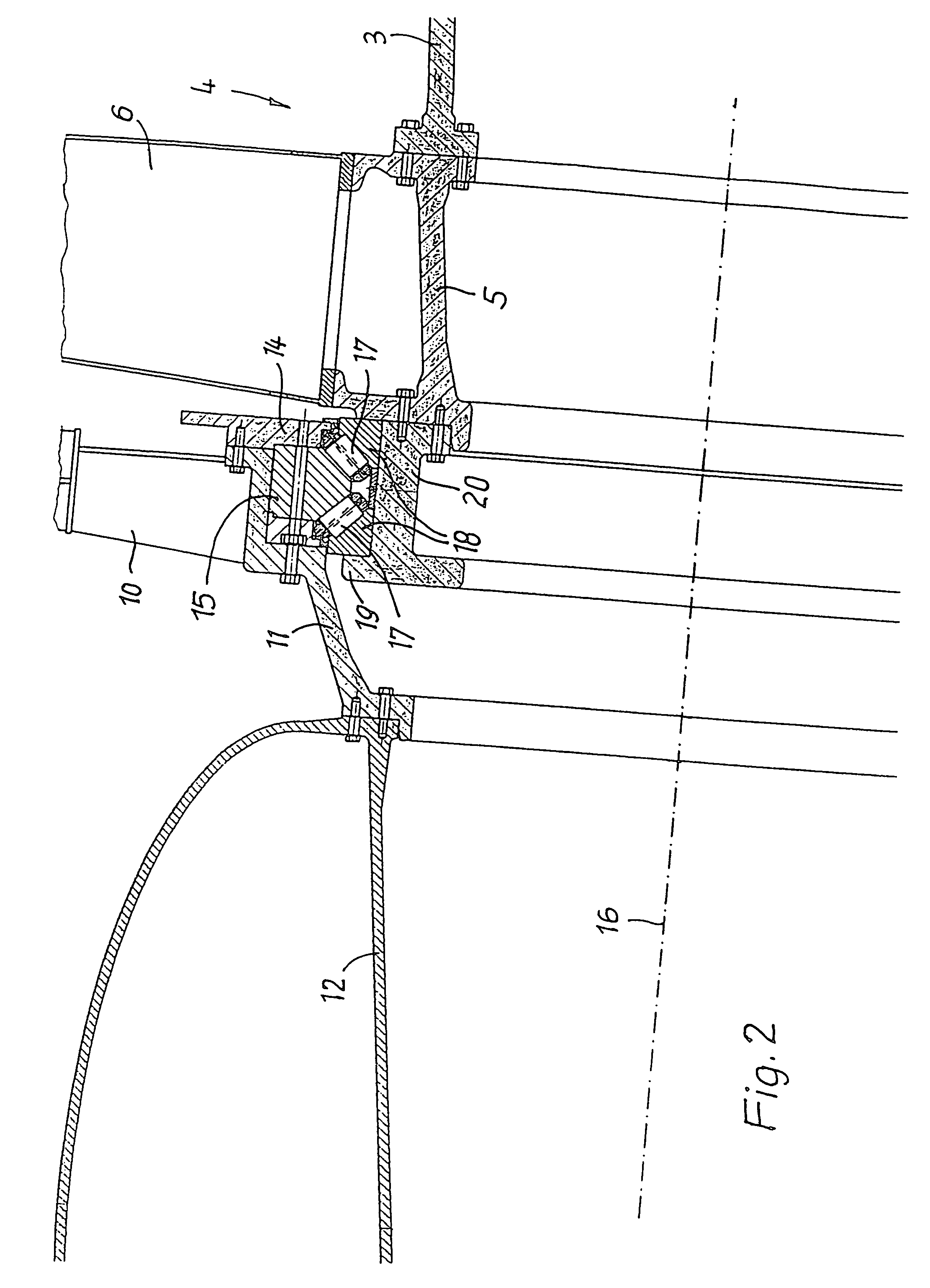
[0006]In the arrangement and configuration of one embodiment, the invention provides that the rotating part of the generator is radially substantially aligned with the bearing. In that way, not only are the axial length of the axis tube member and thus the weight thereof considerably reduced, but in addition the bearing can withstand all moments, even those which fluctuate in their direction, and which occur around axes extending transversely with respect to the axis of the shaft, without the relative position of the generator rotor with respect to the generator stator changing beyond a critical dimension-even in modern installations with a generator diameter of 4000 mm the generator gap may not exceed a width of 3 mm. Moreover, the moment loading on the bearing is reduced by virtue of the radial alignment of the rotating part of the generator with the bearing. In addition, the centrifugal forces which occur upon rotation of the generator rotor can be carried in a particularly problem-free manner by the bearing and operational reliability of the generator is enhanced.
[0008]Preferably the bearing is a twin-row inclined roller bearing with rows of rollers which are arranged in mutually angular relationship. In that case it is particularly provided that each row of rollers includes an angle of about 45° with the axis of the axis tube member and the hollow shaft. That provides for an optimum in terms of the bearing carrying moments. The bearing is desirably arranged next to the machine carrier, wherein the axial length of the axis tube member is substantially restricted to the length of the bearing. The size and the weight of the elements of the wind power installation, which are to be mounted at the top of the pylon, are substantially reduced in that way.

Problems solved by technology

That arrangement admittedly provides that the single bearing does not have to carry any moments and can therefore run with a comparatively low level of wear, but that arrangement suffers from the disadvantage that air gap guidance and control in the generator is not exact and therefore a larger air gap has to be set.
That reduces the level of efficiency of the generator.

Method used


Image

  • Wind energy unit comprising a hollow shaft for rotor hub and generator
  • Wind energy unit comprising a hollow shaft for rotor hub and generator
  • Wind energy unit comprising a hollow shaft for rotor hub and generator

Examples


Embodiment Construction

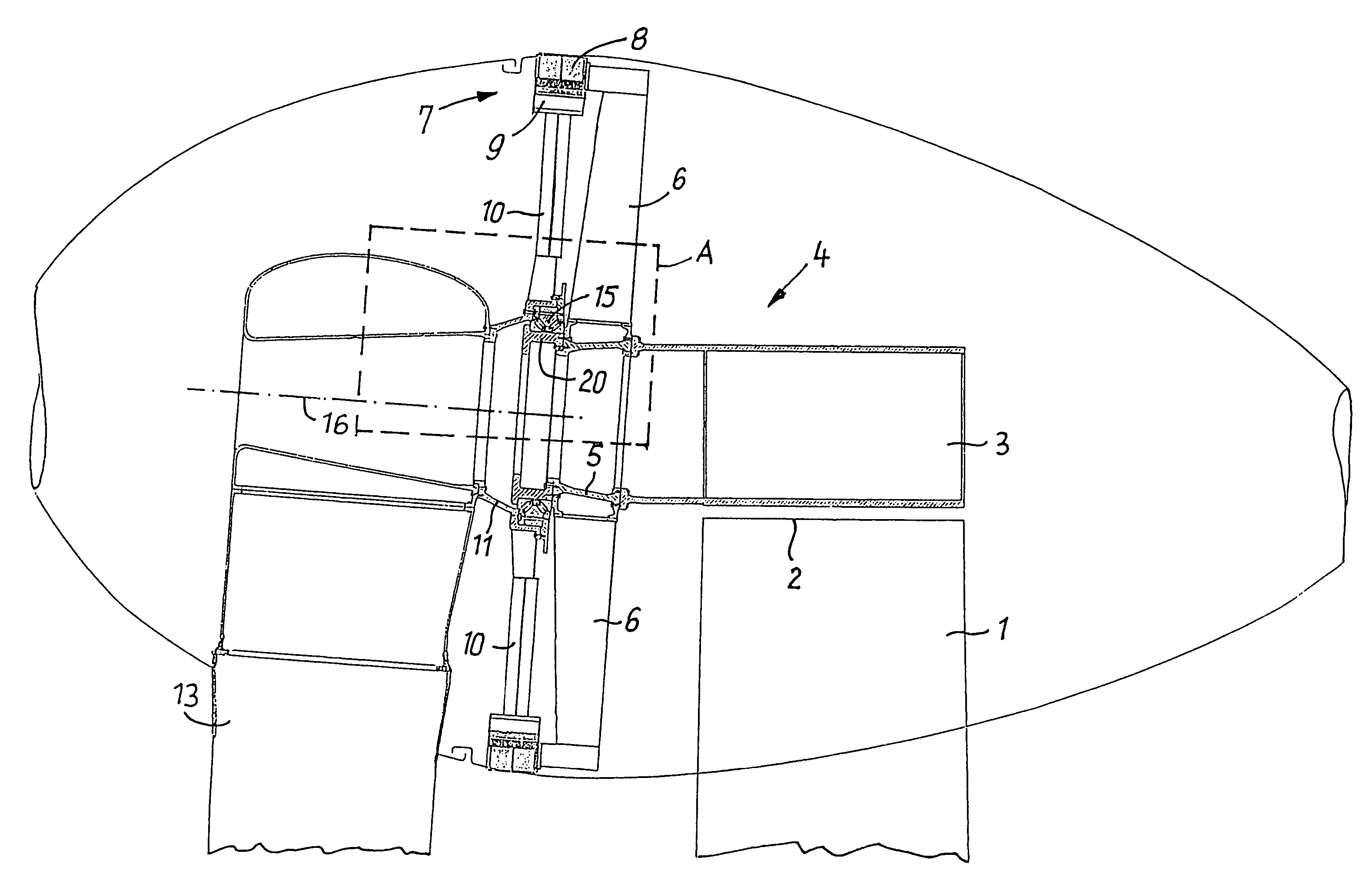
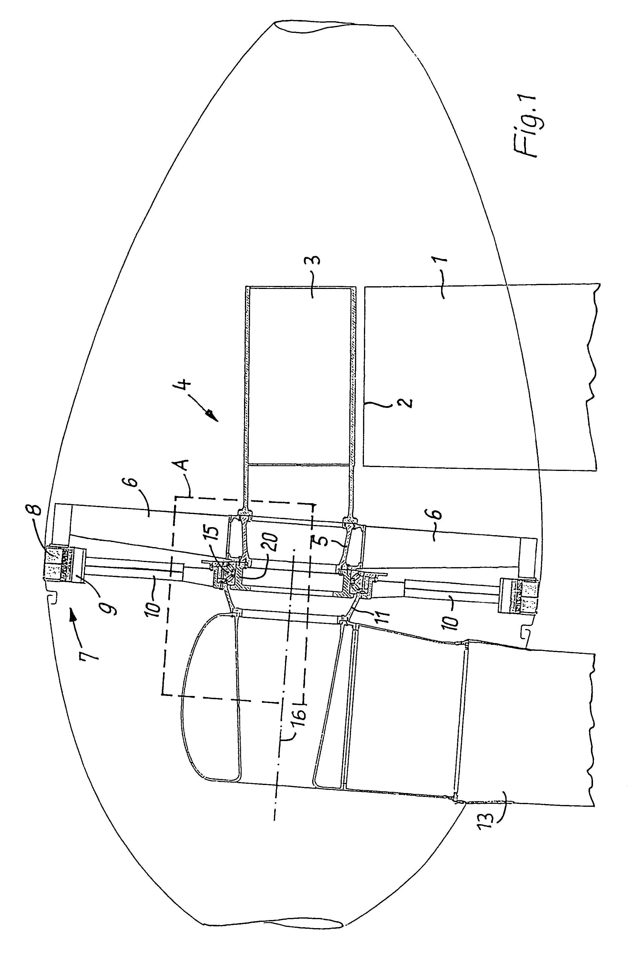
[0012]The housing 3 of a machine carrier which is generally identified by reference 4 is fixed at the upper end (top 2) of a pylon 1 in the usual manner. Fixed to the front end of the housing is the central ring 5 of a star-shaped carrier 6 for the stator 8 of an electrical generator which is generally identified by reference numeral 7; its rotor or armature 9 is arranged in concentric relationship therewith with a narrow gap.

[0013]The rotor 9 of the generator 7 is held by a carrier 10 which is also substantially star-shaped and which is fixed to a hollow shaft 11 to which the hub 12 of the rotor with the rotor blades 13 is flange-mounted in coaxial relationship.

[0014]Jointly with a cover flange 14 the hollow shaft 11—which is of a suitably cranked configuration—encloses the outer race 15 of an inclined roller bearing having two rows of rollers 17 which are arranged inclined at an angle of 45° relative to the axis 16 (and thus at an angle of 90° relative to each other). The inner ra...


PUM


Abstract

In a wind power installation with a (hollow) axis tube member and a hollow shaft mounted thereon for the rotor there is provided only a single bearing which also carries moments, between the axis tube member and the hollow shaft, whereby the parts of the machine which are to be fixed to the machine carrier and thus on the top of the pylon are of a markedly lower weight without the required orientation between the rotating and stationary parts of the electrical generator being adversely affected. In that arrangement the rotating part of the generator is radially aligned substantially with the bearing. The bearing to be used is in particular a twin-row inclined roller bearing with rows of rollers arranged at an angle of about 45° relative to each other.

Description

BACKGROUND OF THE INVENTION[0001]1. Field of the Invention[0002]The invention concerns a wind power installation comprising a machine carrier which is to be fixed to the top of a pylon and which on the one hand holds the static part of an electrical generator and on the other hand supports the rotating part thereof as well as a hub of a rotor which carries rotor blades, wherein the rotor hub and the rotating part of the generator are fixed to a common hollow shaft which is supported by means of a single bearing which also carries moments on an axis tube member which is mounted to the machine carrier.[0003]2. Description of the Related Art[0004]DD 261 395 A1 discloses a wind power installation in which both the axis tube member and also the hollow shaft comprises two cylindrical portions which are spaced in the axial direction and which are of greatly different diameters and which are respectively connected together by a conical portion. Both cylindrical parts of the axis tube member...

Claims


Application Information

Patent Timeline
IPC IPC(8): F03D9/00F03D1/06F03D80/70F16C19/38F16C35/067
CPCF03D1/065F03D11/0008F16C19/386H02K7/1838F16C35/06F05B2220/7066F05B2240/14F05B2250/30F16C2226/60F16C2300/14Y02E10/721Y02E10/722Y02E10/725F16C2360/31F03D80/70Y02E10/72F03D1/06
Inventor WOBBEN, ALOYS
Owner WOBBEN ALOYS
Learn More