Motor, fuel pump, commutator, and method for manufacturing a commutator

Active Publication Date: 2006-08-01
DENSO CORP
View PDF23 Cites 18 Cited by
  • Summary
  • Abstract
  • Description
  • Claims
  • Application Information

AI Technical Summary

Benefits of technology

[0011]In view of the forgoing, it is therefore an object of the present invention to provide a motor in which an increase in axial length thereof is controlled with respect to electrically connecting segments of the same potential. It is another object of the present invention to provide a motor, a fuel pump, a commutator, and a method for manufacturing a commutator, which is capable of preventing discharge wear of the brush and the segments thereof.
[0012]To achieve the above, a motor utilizes a permanent magnet formed from a plurality of magnetically differing poles disposed in an alternating and circumferential fashion, an armature that rotates and that is disposed within an

Problems solved by technology

When discharge occurs between the brush and the segments, there is the possibility of the brush and the segments suffering discharge we

Method used


Image

  • Motor, fuel pump, commutator, and method for manufacturing a commutator
  • Motor, fuel pump, commutator, and method for manufacturing a commutator
  • Motor, fuel pump, commutator, and method for manufacturing a commutator

Examples


Example

First Embodiment

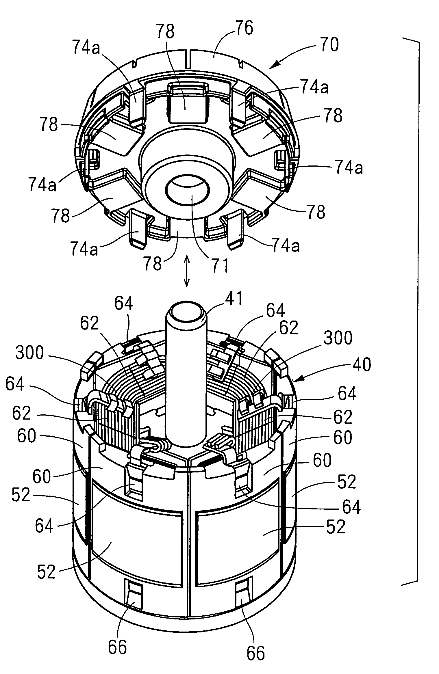
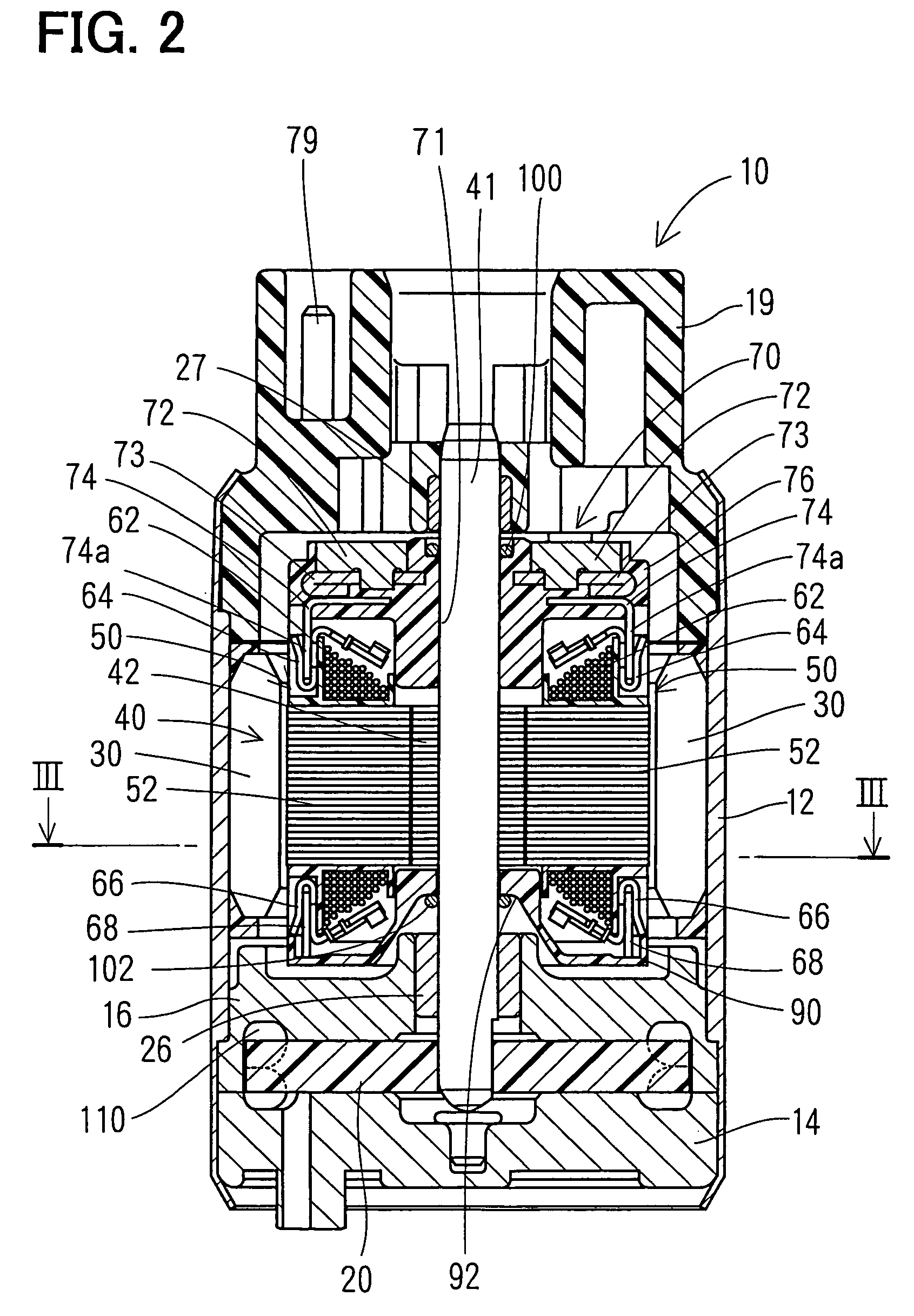
[0057]Referring to FIG. 2, a fuel pump 10 is an in-tank style pump installed, for example, in a vehicle fuel tank. The fuel pump 10 has a housing 12, and an inlet cover 14 and an outlet cover 19 that are secured in place by the housing 12 by means of calking or sealing.

[0058]A pump casing 16 is held between the inlet cover 14 and the housing 12. A C-shaped fluid channel 110 for the pump is formed between the inlet cover 14 and the pump casing 16. The inlet cover 14 and the pump casing 16 are case members in which an impeller 20 is rotatably contained as a rotating member. The inlet cover 14, the pump casing 16, and the impeller 20 constitute a pump portion. The pump casing 16 is the member of the case members containing the impeller 20 which is nearest an armature 40. The pump casing 16 supports a first axle bearing 26 on an inner circumference thereof.

[0059]Several vane grooves are formed on the outer circumferential edge of the disk-shaped impeller 20. When the imp...

Example

Second Embodiment

[0082]A second embodiment according to the present invention is shown in FIGS. 13 and 14. Structural portions thereof which are substantially the same as those of the first embodiment are given the same reference numerals. According to the second embodiment, three of the coils 62 adjacent to each other in the direction of rotation are connected in parallel by a delta connection. Compared to the star connection of the first embodiment, voltage applied to the coils 62 is high, and thus electromagnetic energy built up in the coils 62 is large. Accordingly, the electrostatic capacitance of capacitors 120, which store electromagnetic energy, is sometimes larger than that of the capacitors 78 of the first embodiment within a range such that expression (1) is satisfied.

Example

Third Embodiment

[0083]A third embodiment of a commutator according to the present invention is shown in FIGS. 15A and 15B. Structural portions of the commutator that are substantially the same as those of the first embodiment are given the same reference numerals. A commutator 130 according to the third embodiment has a first formed body 140 near the segments 72, and a second formed body 150 near capacitors 260 (not shown in FIGS. 15A and 15B, but discussed later). Each member of the first formed body 140 is supported by a first insulating resin portion 142, and each member of the second formed body 150 is supported by a second insulating resin portion 152. Claws 132, which are a portion of the commutator terminals of the commutator 130, have first connecting claws 234 of first connecting terminals 232 (discussed later) of the first formed body 140, and second connecting claws 255 of second connecting terminals 254 (discussed later) of the second formed body 150 that are electricall...


PUM


Abstract

A commutator includes six segments disposed in the direction of rotation, and is attached to one axial end of an armature. By the commutator rotating together with the armature, each of the segments successively contacts a brush. Each of the segments is electrically connected with terminals through mid-terminals. Three of the six terminals, non-adjacent and alternatingly located in the direction of rotation, are electrically connected directly with mid-terminals facing in radial opposition. Capacitors are electrically connected directly with the terminals adjacent in the direction of rotation. Discharge does not occur between the brush and segments when the brush separates from the segments accompanying rotation of the armature, since electromagnetic energy built up in the coils of the armature is temporarily built up in the capacitors.

Description

CROSS REFERENCE TO RELATED APPLICATIONS[0001]This application is based upon, claims the benefit of priority of, and incorporates by reference Japanese Patent Application No. 2003-13460 filed Jan. 22, 2003, No. 2003-100050 filed Apr. 3, 2003, No. 2003-103847 filed Apr. 8, 2003, and No. 2003-326344 filed Sep. 18, 2003.BACKGROUND OF THE INVENTION[0002]1. Field of the Invention[0003]The present invention relates to a motor, a fuel pump, a commutator, and a method for manufacturing a commutator.[0004]2. Description of the Related Art[0005]Motors are known that use a commutator having a plurality of segments disposed in a circular fashion in the direction of rotation and that are electrically connected with coils wound around an armature, such that drive current supplied to the armature is converted by brushes that successively contact the segments accompanying rotation of the armature. Japanese Patent Publication No. Hei 7-85642 discloses such a motor.[0006]In this sort of motor, there a...

Claims


Application Information

Patent Timeline
IPC IPC(8): H02K13/00F04D5/00H01R39/04H01R43/06H02K1/24H02K11/02H02K13/04H02K13/06H02K23/30H02K23/66
CPCF04D5/002H02K1/24H02K23/66H02K13/006H02K13/04H02K13/06H02K23/30H01R39/04H01R43/06H02K11/028
Inventor MOROTO, KIYONORIITO, MOTOYAKIYOS, KENZOIWANARI, EIJIKOBAYASHI, MASAYUKI
Owner DENSO CORP
Why Eureka
Try Eureka