Liquid crystal display and driving method thereof

Inactive Publication Date: 2006-08-01
LG DISPLAY CO LTD
View PDF7 Cites 20 Cited by
  • Summary
  • Abstract
  • Description
  • Claims
  • Application Information

AI Technical Summary

Benefits of technology

[0021]Accordingly, it is an object of the present invention to provide a liquid crystal display and a driving method there

Problems solved by technology

Such a conventional LCD driving method causes a phenomenon in which a data is distorted due to a coupling capacitor Cs between the data line

Method used


Image

  • Liquid crystal display and driving method thereof
  • Liquid crystal display and driving method thereof
  • Liquid crystal display and driving method thereof

Examples


first embodiment

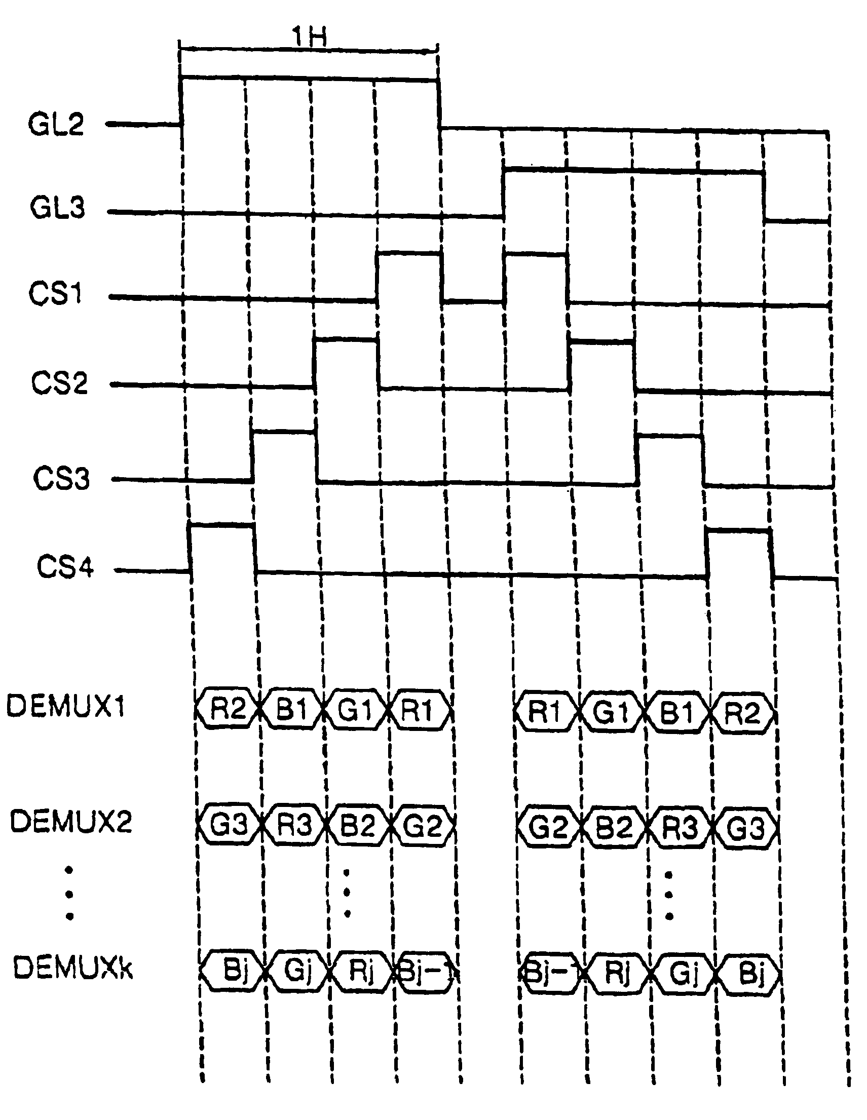
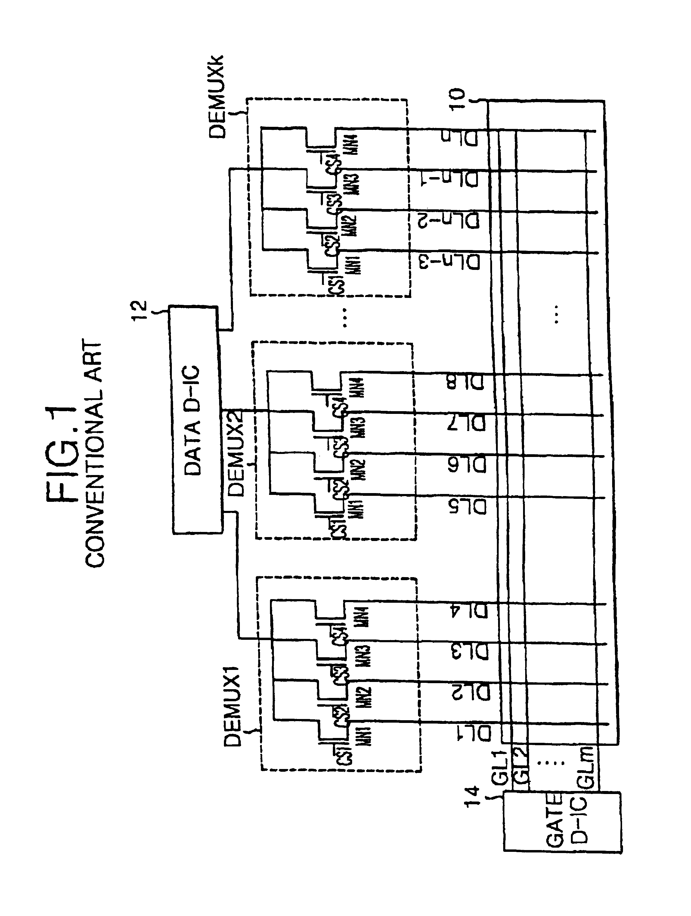
[0034]FIG. 5 shows a driving method for a liquid crystal display according to the present invention. Such a driving method will be described in conjunction with the liquid crystal display shown in FIG. 1.

[0035]Referring to FIG. 5, in the driving method according to the first embodiment of the present invention, a sequence of control signals Cs is converted every horizontal period. In other words, when a gate scanning signal GSS is applied to a second gate line GL2, demultiplexors DEMUX1 to DEMUXk reverse-sequentially supply four data to data lines DL1 to DLn. To the contrary, when the gate scanning signal GSS is applied to a third gate line GL3, the demultiplexors DEMUX1 to DEMUXk sequentially supply four data to the data lines DL1 to DLn. In other words, in the first embodiment of the present invention, if a data is sequentially sent in a certain horizontal period, then the data is reverse-sequentially sent in the next horizontal period. To this end, a sequence of the control signa...

second embodiment

[0046]FIG. 7A and FIG. 7B are waveform diagrams for showing a driving method according to the present invention.

[0047]Referring to FIG. 7A and FIG. 7B, in the driving method according to the second embodiment of the present invention, a sequence of the control signals CS1 to CS4 is changed every frame. In other words, the control signals CS1 to CS4 are sequentially applied in the first and fourth frames while being reverse-sequentially applied in the second and third frames. Accordingly, a change frequency of the data signal applied to the data lines DL1 to DLn and a leakage current becomes uniform averagely, thereby obtaining a visually uniform picture. The setting of a conversion frequency of the control signals CS1 to CS4 to four frames in the second embodiment of the present invention aims to prevent a generation of a direct current offset voltage from each pixel. In other words, when the liquid crystal display panel 10 is driven in a dot inversion, each data line DL1 to DLn is ...


PUM


Abstract

A method of driving a liquid crystal display wherein an application sequence of a data is changed, to thereby improve a picture quality. In the method, the data is supplied to a desired number of data lines on a basis of first sequence in a first horizontal period. The data is supplied to the desired number of data lines on a basis of second sequence in a second horizontal period following the first horizontal period.

Description

BACKGROUND OF THE INVENTION[0001]1. Field of the Invention[0002]This invention relates to a liquid crystal display, and more particularly to a liquid crystal display and a driving method wherein an application sequence of a data is changed so as to improve a picture quality.[0003]2. Description of the Related Art[0004]Generally, a liquid crystal display (LCD) uses a pixel matrix arranged in each intersection between gate lines and data lines to thereby display a picture corresponding to video signals. Each pixel consists of a liquid crystal cell controlling a transmitted light quantity in accordance with a video signal, and a thin film transistor (TFT) for switching the video signal to be applied from the data line to the liquid crystal cell.[0005]The LCD is provided with gate and data driving integrated circuits, hereinafter referred to as “D-IC's”, for driving the gate lines and the data lines. In this case, a demultiplexor (DEMUX) is connected between the data D-IC so as to simpl...

Claims


Application Information

Patent Timeline
IPC IPC(8): G09G3/36G09G3/00
CPCG09G3/3688G09G2310/0297G09G2310/0283G02F1/133
Inventor YEO, JU CHUNKIM, SEONG GYUN
Owner LG DISPLAY CO LTD
Why Eureka
Try Eureka