System and method for image based sensor calibration

a sensor and image technology, applied in the field of image guided medical systems, can solve the problems of difficult visualization, inability to physically measure the pose of the points in the image plane, and patient anatomy, and achieve the effects of accurate, free-hand calibration, and easy detection

Inactive Publication Date: 2006-08-01
SURGICAL NAVIGATION TECH
View PDF488 Cites 116 Cited by
  • Summary
  • Abstract
  • Description
  • Claims
  • Application Information

AI Technical Summary

Benefits of technology

[0011]The invention allows for accurate, free-hand calibration of a tracked instrument which can be performed by minimally trained personnel. The calibration jig may be a sterile object and used within an operating room prior to the performance of a surgical procedure. Furthermore, problems associated with the calibration jig or the imaging system can easily be detected by inspection of the images as the calibration is being performed.

Problems solved by technology

These systems are typically used when the visualization of a surgical tool could be obscured by a patient's anatomy, or when the surgical tool is visible but the patient's anatomy could be difficult to visualize.
Ultimately, the calibration problem involves determining the position and orientation (POSE) of a set of points displayed by the image plane in the space defined by the tracking markers of the tracked instrument.
However, it is not possible to physically measure the POSE of the points in the image plane.

Method used


Image

  • System and method for image based sensor calibration
  • System and method for image based sensor calibration
  • System and method for image based sensor calibration

Examples


Embodiment Construction

[0029]Reference will now be made in detail to the present preferred embodiments of the invention, examples of which are illustrated in the accompanying drawings. Wherever possible, the same reference numbers will be used throughout the drawings to refer to the same or like parts.

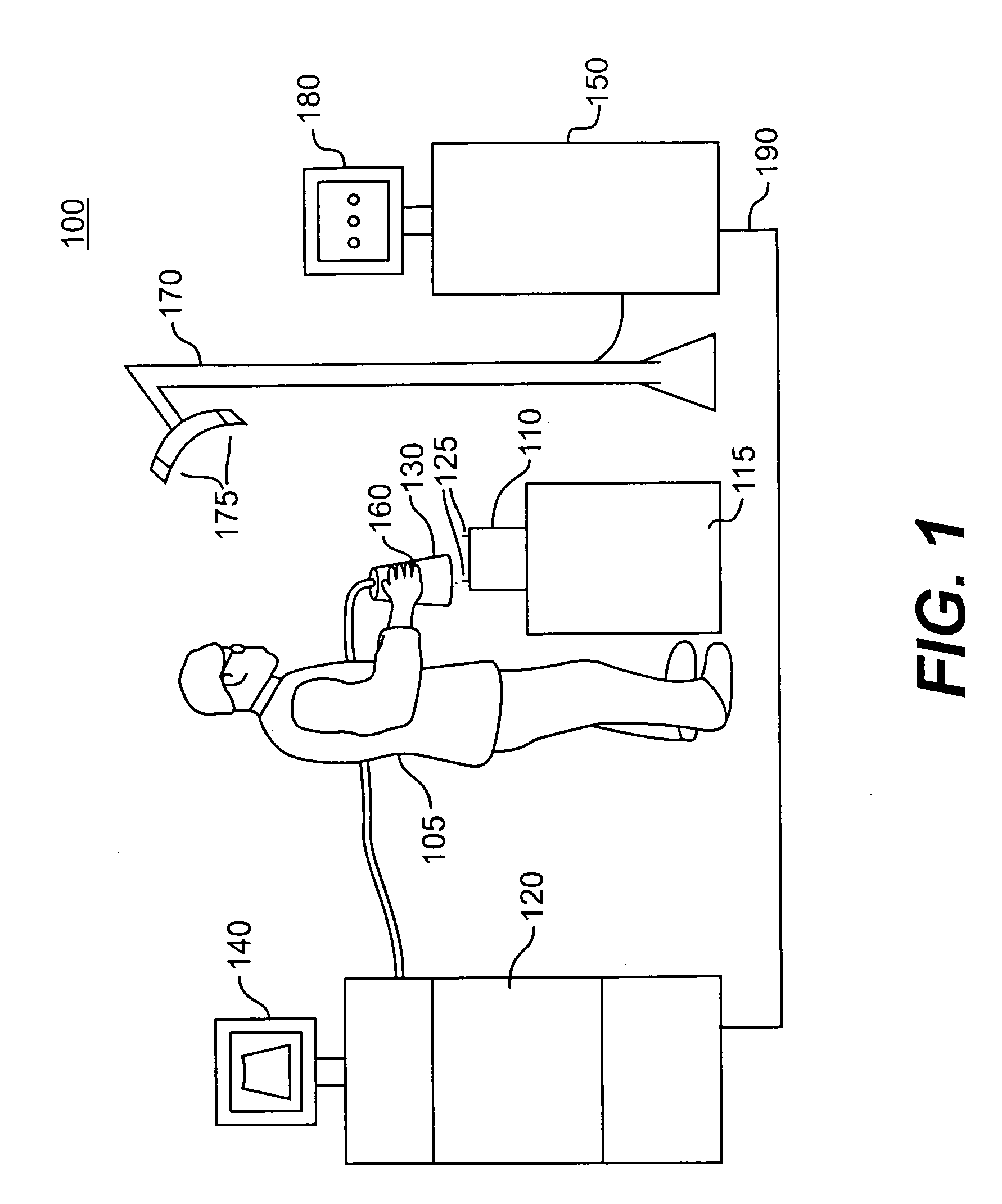
[0030]FIG. 1 illustrates an exemplary calibration system and method 100 which is consistent with the present invention. Stationary calibration jig 110 supported by platform 115 is scanned by technician 105 by manipulating probe 130. Probe 130 comprises a transducer which transmits signals in the direction of the jig 110. Signals reflected from jig 110 can then be received by probe 130 and fed by cable to imaging system 120. Imaging system 120 processes the received signals and forms images which can be displayed on monitor 140. In the preferred embodiment imaging system 120 is a standard ultrasonic imaging system; however, it should be appreciated that other types of imaging systems, such as microwave, X-ray...


PUM


Abstract

Apparatus and methods are disclosed for the calibration of a tracked imaging probe for use in image-guided surgical systems. The invention uses actual image data collected from an easily constructed calibration jig to provide data for the calibration algorithm. The calibration algorithm analytically develops a geometric relationship between the probe and the image so objects appearing in the collected image can be accurately described with reference to the probe. The invention can be used with either two or three dimensional image data-sets. The invention also has the ability to automatically determine the image scale factor when two dimensional data-sets are used.

Description

BACKGROUND OF THE INVENTION[0001]1. Field of Invention[0002]The present invention is directed generally to image guided medical systems, and more particularly, to systems and methods for utilizing data collected from imaging sensors to calibrate a tracking device.[0003]2. Description of the Related Art[0004]Image guided surgical techniques have been used with success in aiding physicians for performing a wide variety of delicate surgical procedures. These systems are typically used when the visualization of a surgical tool could be obscured by a patient's anatomy, or when the surgical tool is visible but the patient's anatomy could be difficult to visualize.[0005]In order for these systems to be effective, points of the patient's anatomy appearing in the image must be accurately correlated to the instrument being tracked by the surgical navigation system. Accomplishing this correlation requires the accurate calibration of the tracking device. Ultimately, the calibration problem invo...

Claims


Application Information

Patent Timeline
Patent Type & Authority Patents(United States)
IPC IPC(8): G06K9/00
CPCA61B19/52A61B19/5244G06T7/0018G06T7/004A61B2017/00725G06T2207/30004A61B2019/5276A61B34/20A61B90/36A61B2090/378G06T7/70G06T7/80
Inventor HOLSING, TROYGOODCHILD, GORDON
Owner SURGICAL NAVIGATION TECH
Why Eureka
Try Eureka