Slipping contact line model and the mass-conservative level set implementation for ink-jet simulation

Inactive Publication Date: 2006-08-01
SEIKO EPSON CORP
View PDF8 Cites 19 Cited by
  • Summary
  • Abstract
  • Description
  • Claims
  • Application Information

AI Technical Summary

Benefits of technology

[0008]According to one aspect of this invention, a method for simulating and analyzing fluid flow through, and ejection from, a channel is provided. The method comprises the steps of: (a) setting a pressure indicative of the flow of a first fluid into the channel; (b) calculating, based on the inflow pressure of the first fluid, (i) the flow velocity of the first fluid through the channel, (ii) a triple point formed at the intersection of the first fluid, a second fluid and a wall of the channel, and (iii) a pressure related to the flow of the first fluid through the channel, wherein, in making the calculations in step (b), a free-slip boundary condition is imposed near the triple point allowing the triple point to move if a contact angle between the first fluid and a channel wall is greater than or equal to a first angle value or if the contact angle is less or equal to a second angle value which is less than the first angle value, and a surface tension is included as a body force term in the calculation of the flow velocity of the first fluid through the channel; and (c) simulating the flow of the first fluid through, and ejection from, the channel.
[0009]The following features

Problems solved by technology

Existing fluid flow models tend to impose certain conditions that lead to problems.
While this simplifies the computations, it is unrealistic.
There are other problems that are typically encountered in trying to numerically simulate fluid flow with s

Method used


Image

  • Slipping contact line model and the mass-conservative level set implementation for ink-jet simulation
  • Slipping contact line model and the mass-conservative level set implementation for ink-jet simulation
  • Slipping contact line model and the mass-conservative level set implementation for ink-jet simulation

Examples


Embodiment Construction

A. Introduction

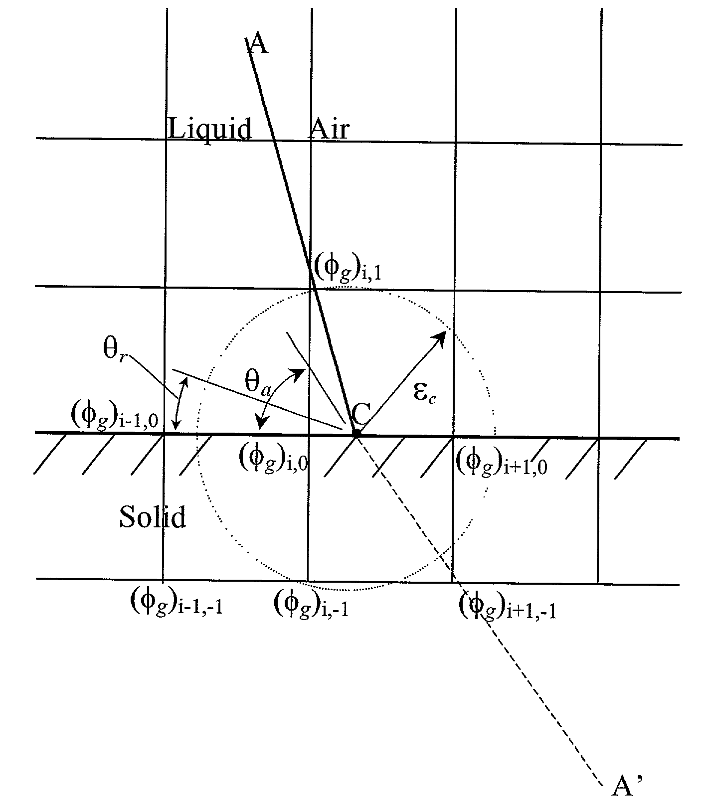
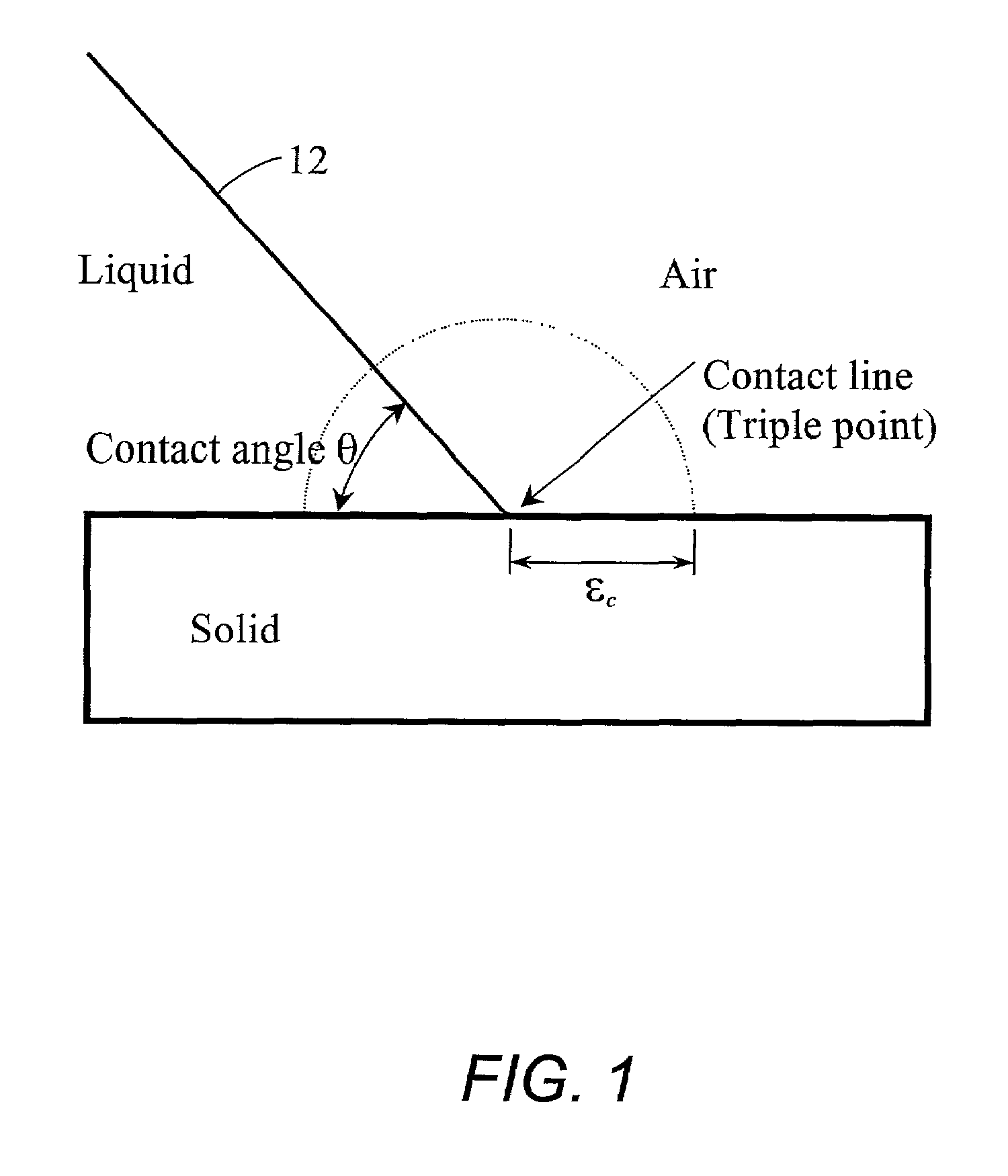
[0025]As shown in FIG. 1, a “contact line” is formed at the intersection of two immiscible fluids (a liquid and air, for example) and a solid. In two space dimensions, the contact line is a straight line perpendicular to the paper. In three-dimensional axi-symmetric spaces, the contact line is actually a loop. A “contact line” is also called “triple point” because it is the point (or the line or the curve) where the three phases (two fluids and a solid) meet each other. Note that “slipping contact line,”“contact line,” and “triple point” will be used interchangeably herein. In many fluid systems, the interaction between the three phases in the immediate vicinity of a contact line can significantly affect the statics as well as the dynamics of the two immiscible fluids. Capillary tubes, spreading petroleum on ice, and ink flows in a print head nozzle are just a few examples. In attempting to numerically simulate fluid flow with a slipping contact line, one encounters s...


PUM


Abstract

A macroscopic physical model simulates and analyzes ink ejection from a piezoelectric print head. The model handles the slipping contact line problem and introduces a mass-conservative finite difference implementation using the level set method. First, the critical angle approach is adopted. The triple point is allowed to move if the critical angle is exceeded. Second, the no-slip boundary condition in the neighborhood of the triple point is relaxed and substituted by the free-slip boundary condition. Third, to allow the triple point to quickly accelerate when the critical angle is exceeded, an extra surface tension is added as a body force term in the governing equation. Fourth, the level set method is adopted to implement the slipping contact line model. Finally the above idea is incorporated in a fluid solver based on the higher-order projection method.

Description

BACKGROUND OF THE INVENTION[0001]1. Field of the Invention[0002]The present invention provides a macroscopic physical model to simulate and analyze ink ejection from a piezoelectric print head. More particularly, the model of this invention addresses the slipping contact line problem and introduces a mass-conservative finite difference implementation using the level set method so that more precise control of ink droplet size and shape can be achieved. The model may be embodied in software, hardware or combination thereof and may be implemented on a computer or other processor-controlled device.[0003]2. Description of the Related Art[0004]More precise control over the ink ejection process, and in particular ink droplet size, can improve the quality of the final printed product. To achieve such control, however, requires a model that accurately simulates fluid flow including droplet size and shape. Existing fluid flow models tend to impose certain conditions that lead to problems. For...

Claims


Application Information

Patent Timeline
IPC IPC(8): G06G7/48G06G7/50B41J2/01G06F17/50G06F19/00
CPCG06F17/5018G06F2217/16G06F2111/10G06F30/23
Inventor YU, JIUN-DERSAKAI, SHINRI
Owner SEIKO EPSON CORP
Why Eureka
Try Eureka