Method and remote-controlled reflector device for layout axis lines during construction of a building in the absence of direct line of sight

Inactive Publication Date: 2006-08-08
MAKOTINSKY VALENTIN
View PDF32 Cites 20 Cited by
  • Summary
  • Abstract
  • Description
  • Claims
  • Application Information

AI Technical Summary

Benefits of technology

[0024]It is another object of the present invention to provide a remote-controlled device allowing alignment of the line of sight between two desired points by reflecting it through an adjustable mirror.
[0025]I

Problems solved by technology

It is apparent that this alignment procedure is time-consuming and requires the combined effort of several different individuals at different locations in the area to be surveyed.
It does not disclose on-command alignment in a land surveying procedure.
It does not disclose a remotely controlled land surveying assist device for aligning on-command the same with a remote field location.
The Hansen patent (U.S. Pat. No. 3,580,687) discloses a surveying instrument, which detects when it is misaligned, but it provides no means for on-command alignment.
It is apparent that none of the last four mentioned patents disclose instruments useful for land surveying operations.
For buildings of greater height this method is not practical

Method used


Image

  • Method and remote-controlled reflector device for layout axis lines during construction of a building in the absence of direct line of sight
  • Method and remote-controlled reflector device for layout axis lines during construction of a building in the absence of direct line of sight
  • Method and remote-controlled reflector device for layout axis lines during construction of a building in the absence of direct line of sight

Examples


Embodiment Construction

[0037]A detailed description of the present invention follows with reference to accompanying drawings in which like elements are indicated by like reference letters and numerals.

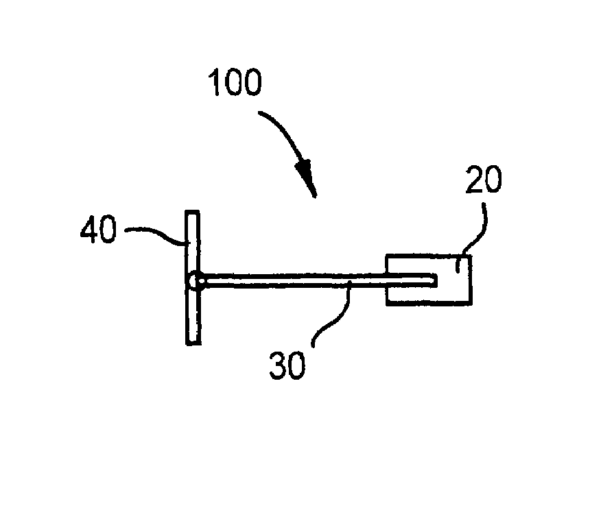
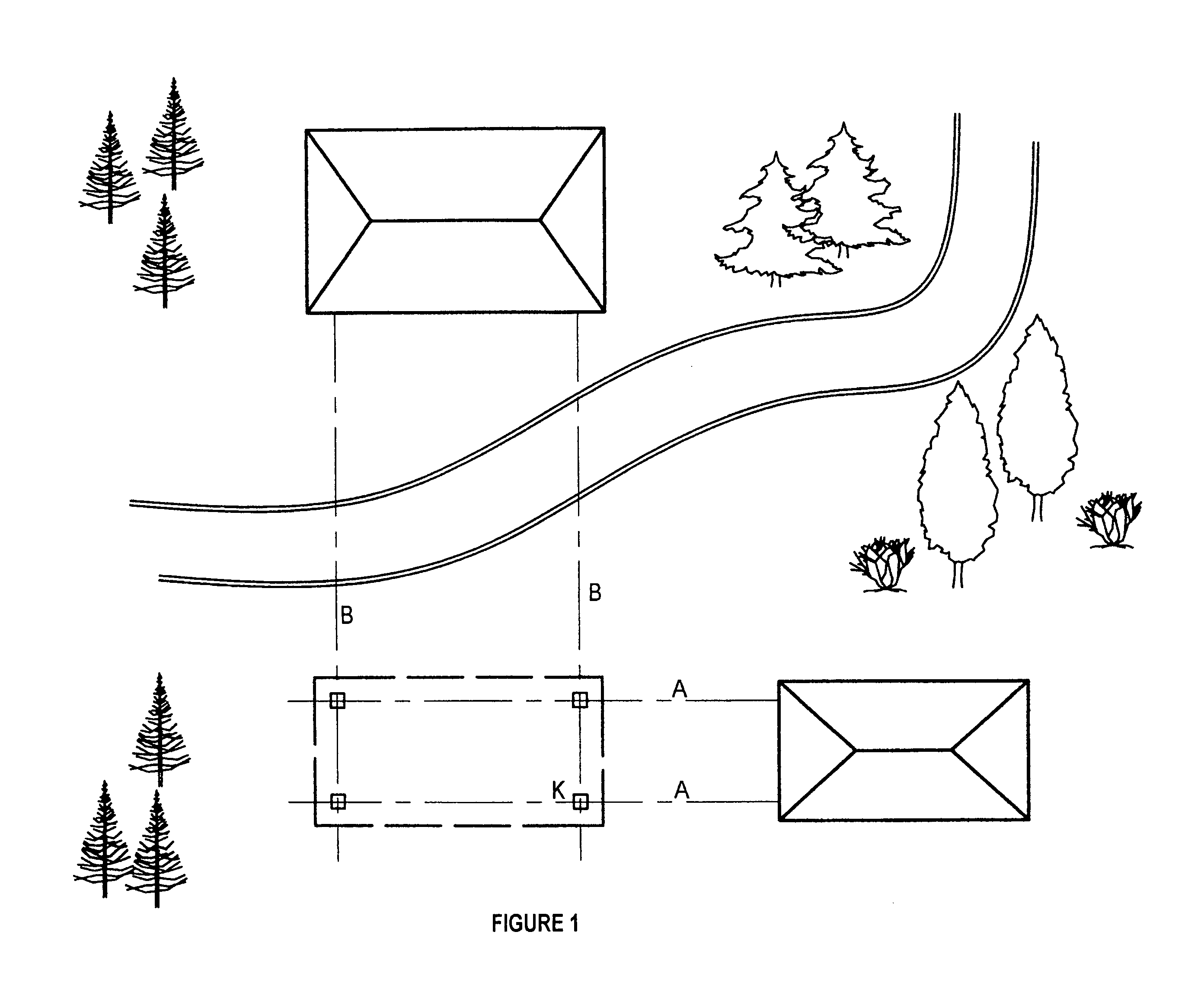
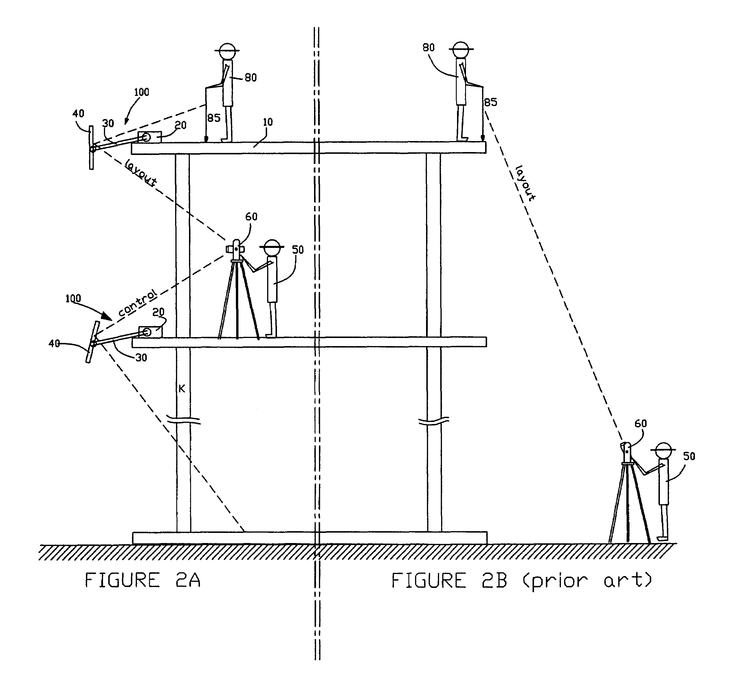
[0038]FIG. 1 illustrates the general location of the axis lines of a building under construction in relation to other objects nearby. FIG. 2A illustrates the use of the reflector device 100 according to the method of the invention. It is based on the general procedure of transfer of axis lines as described above. The general schematic depiction of the reflector device 100 is shown on FIG. 3A and FIG. 3B and includes a base equipped with a remote-controlled servomotor drive 20, an extension pipe 30 containing an position adjustment means, and a mirror 40 capable of rotating about its horizontal and vertical axis.

[0039]The remote-controlled drive 20 can be made as a mechanically (spring-loaded, telescopic), manually, pneumatically, hydraulically or electrically driven stand-alone apparatus driving the position...


PUM


Abstract

A method and remote-controlled reflector device for layout reference and axis lines is provided for use preferably in high building construction industry. The reflector device includes a mirror capable of rotating about its horizontal and vertical axes as controlled by an instrument man standing with a remote controller and a theodolite at a first location, such as on the ground or a lower floor of the building. The reflector device is positioned over the edge of a floor of a building under construction such as to be in direct view from both the first location and the second location where the new axis line marking are to be placed by the rod man. The mirror is first rotated by the instrument man such as to reflect the view from the theodolite back upon itself to verify its proper alignment with the base axis line. The instrument man then remotely rotates the mirror towards the second location such that the inflected line of sight is formed from the theodolite through the mirror defining an inflection point and advises the rod man where to place the mark for the new axis line. The procedure is then repeated at other locations as needed. The method allows more precise and safe transfer of lines without the need for the rod man to stand close to the edge of the building. Proper verification of the existing layouts is also described.

Description

BACKGROUND OF THE INVENTION[0001]The present invention relates generally to marking devices and methods for land surveying and building construction. More particularly, the device and method of the invention utilizes a remote-controlled mirror device to deflect the line of sight or beam pathways of leveling devices. That in turn allows easier and safer transfer of the axis lines of a multi-story building under construction from one floor to the next as well as over any other obstacles to a direct line of sight.[0002]During the building construction, the main objective of the operator is to mark down the axis lines of the future building. This step of layout is typically conducted before the actual excavation and building construction begins. Various well-defined objects are used as basis for the markings such as existing nearby buildings, previously marked property lines, etc.[0003]It is a common practice to layout the axis lines of the building outside the actual construction zone ...

Claims


Application Information

Patent Timeline
IPC IPC(8): G01C15/00
CPCG01C15/006G01C15/002
Inventor MAKOTINSKY, VALENTIN
Owner MAKOTINSKY VALENTIN
Why Eureka
Try Eureka