Pile fabric
- Summary
- Abstract
- Description
- Claims
- Application Information
AI Technical Summary
Benefits of technology
Problems solved by technology
Method used
Image
Examples
example 1
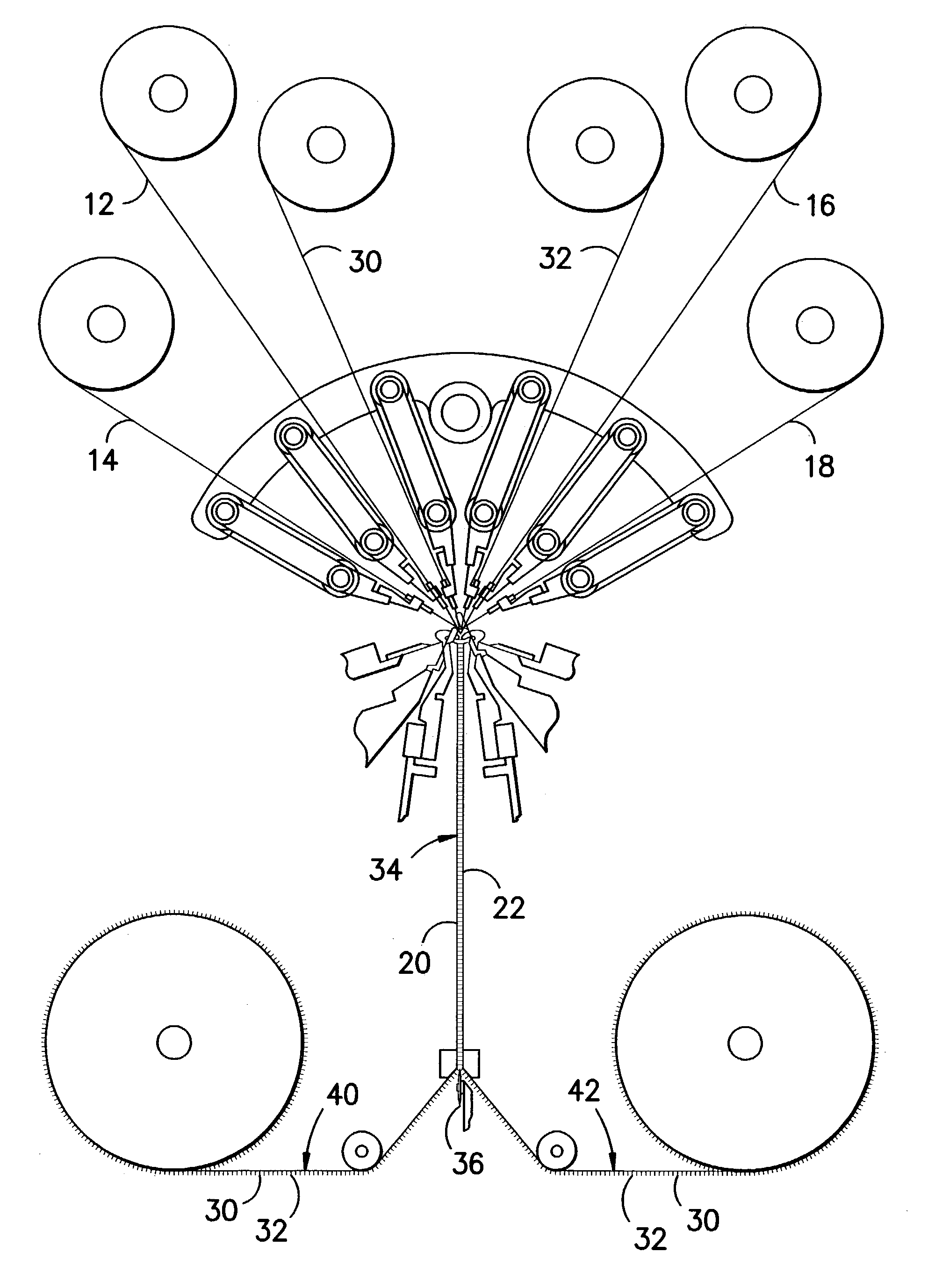
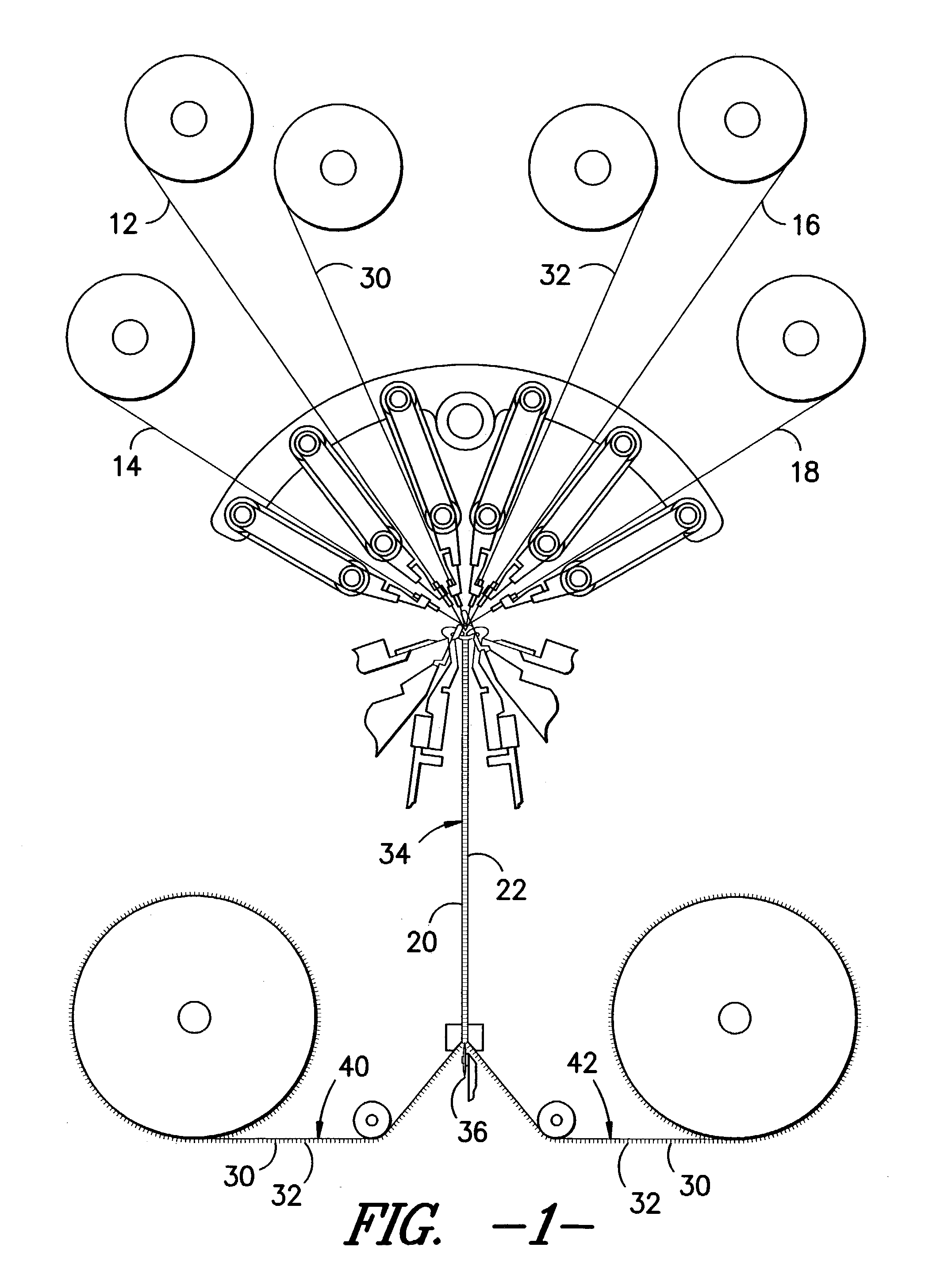
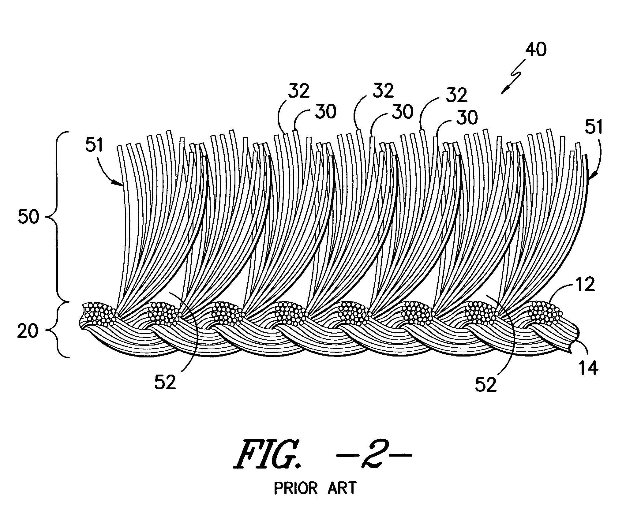
[0038]A 44 gauge double needle bar knit stitch fabric was formed in a sandwich structure at a six bar construction with ground yarns (forming the fabric base) carried in bars 1, 2, 5 and 6 and pile yarns carried in bars 3 and 4. The pile-forming yarns were characterized by variable shrinkage characteristics. The ground yarns carried in bars 1 and 6 were 100 denier 34 filament semi-dull round false twist textured polyester with post texturing entanglement. The ground yarns carried in bars 2 and 5 were 100 denier 36 filament spun drawn flat polyester yarns. Two different pile-forming yarns were used with each yarn being fully threaded through both bars 3 and 4 such that each pile tuft contains both pile-forming yarns. The first pile-forming yarn which was characterized by residual heat shrinkage potential of about 1 to 2 percent was a 160 denier 48 filament partially oriented full dull polyester yarn formed from filaments with a lobal wave shaped cross-section. This yarn was cold draw...
example 2
[0043]A 44 gauge double needle bar knit stitch fabric was formed in a sandwich structure at a six bar construction with ground yarns (forming the fabric base) carried in bars 1, 2, 5 and 6 and pile yarns carried in bars 3 and 4. The pile-forming yarns were characterized by variable shrinkage characteristics. The ground yarns carried in bars 1 and 6 were 100 denier 34 filament semi-dull round false twist textured polyester with post texturing entanglement. The ground yarns carried in bars 2 and 5 were 100 denier 36 filament semi-dull round spun drawn flat polyester. Two pile-forming yarns were used such that each pile tuft contains both pile-forming yarns.
[0044]The bar 3 yarn which was characterized by residual heat shrinkage potential of about 7 to about 8.5 percent was a 175 denier 48 filament partially oriented full dull round polyester yarn formed from filaments with a substantially circular cross-section and cold drawn to 100 denier before fabric formation according to the proce...
examples 3 – 5 (
EXAMPLES 3–5 (COMPARATIVE)
[0049]In order to evaluate the differences between fabric of the present invention and standard pile fabrics, the pile height differential between pairs of randomly selected fibers was measured in a series of pile fabrics wherein the pile yarn did not have variable shrinkage characteristics. All fabrics were 44 gauge double needle bar knit stitch construction. Finishing was carried out in accordance with the procedures outlined in Example 1.
PUM
 Abstract
Description
Claims
Application Information
 - R&D
- Intellectual Property
- Life Sciences
- Materials
- Tech Scout
- Unparalleled Data Quality
- Higher Quality Content
- 60% Fewer Hallucinations
Browse by: Latest US Patents, China's latest patents, Technical Efficacy Thesaurus, Application Domain, Technology Topic, Popular Technical Reports.
© 2025 PatSnap. All rights reserved.Legal|Privacy policy|Modern Slavery Act Transparency Statement|Sitemap|About US| Contact US: help@patsnap.com


