

Personal compact cart
a compact cart and compact technology, applied in the field of personal vehicles, can solve the problems of limiting the autonomy of golf carts equipped with combustion engines, affecting the safety of passengers, etc., and achieves the effect of reducing the number of components and its size, without compromising stability, and low weigh
- Summary
- Abstract
- Description
- Claims
- Application Information
AI Technical Summary
Benefits of technology
Problems solved by technology
Method used
Image

Examples
first embodiment
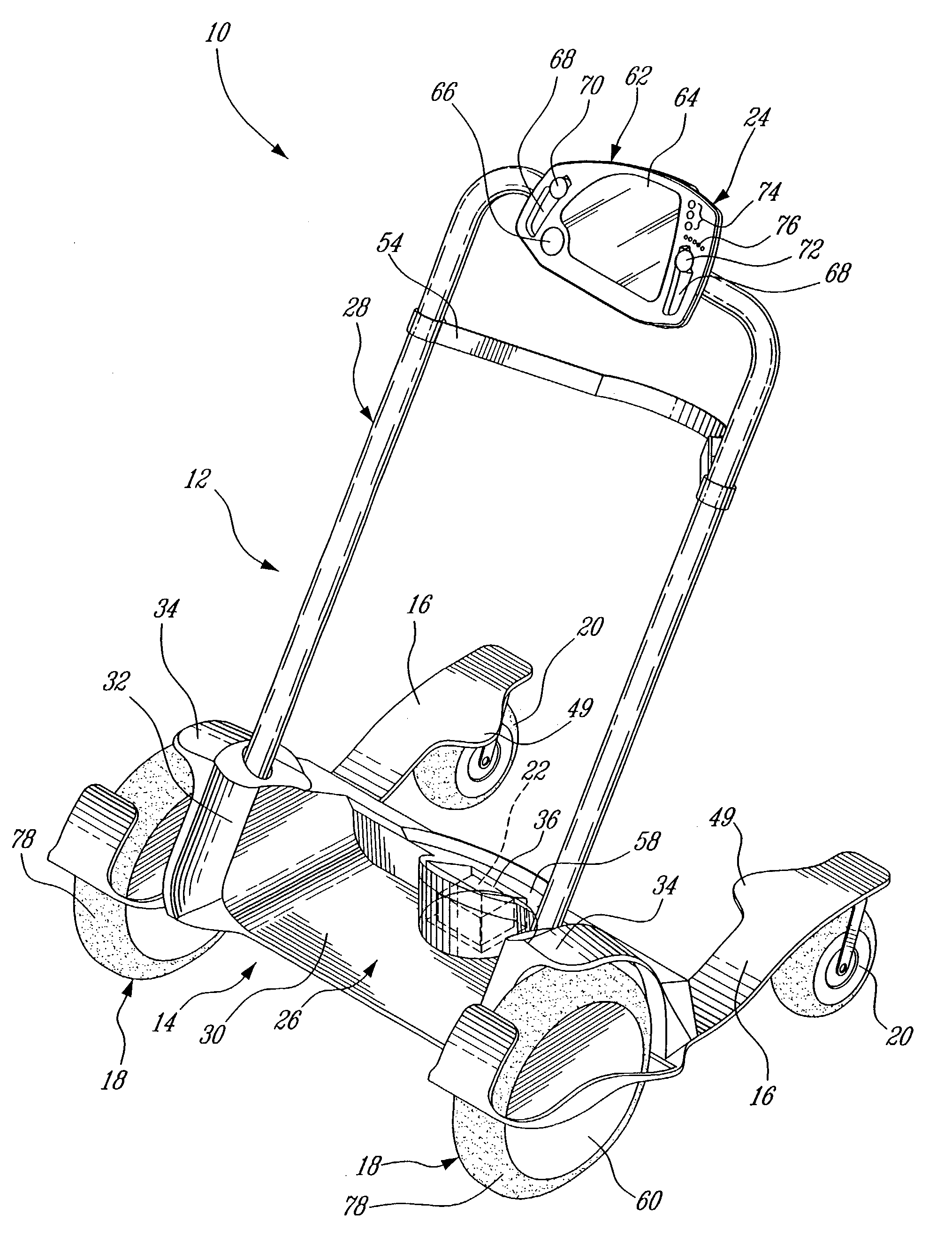
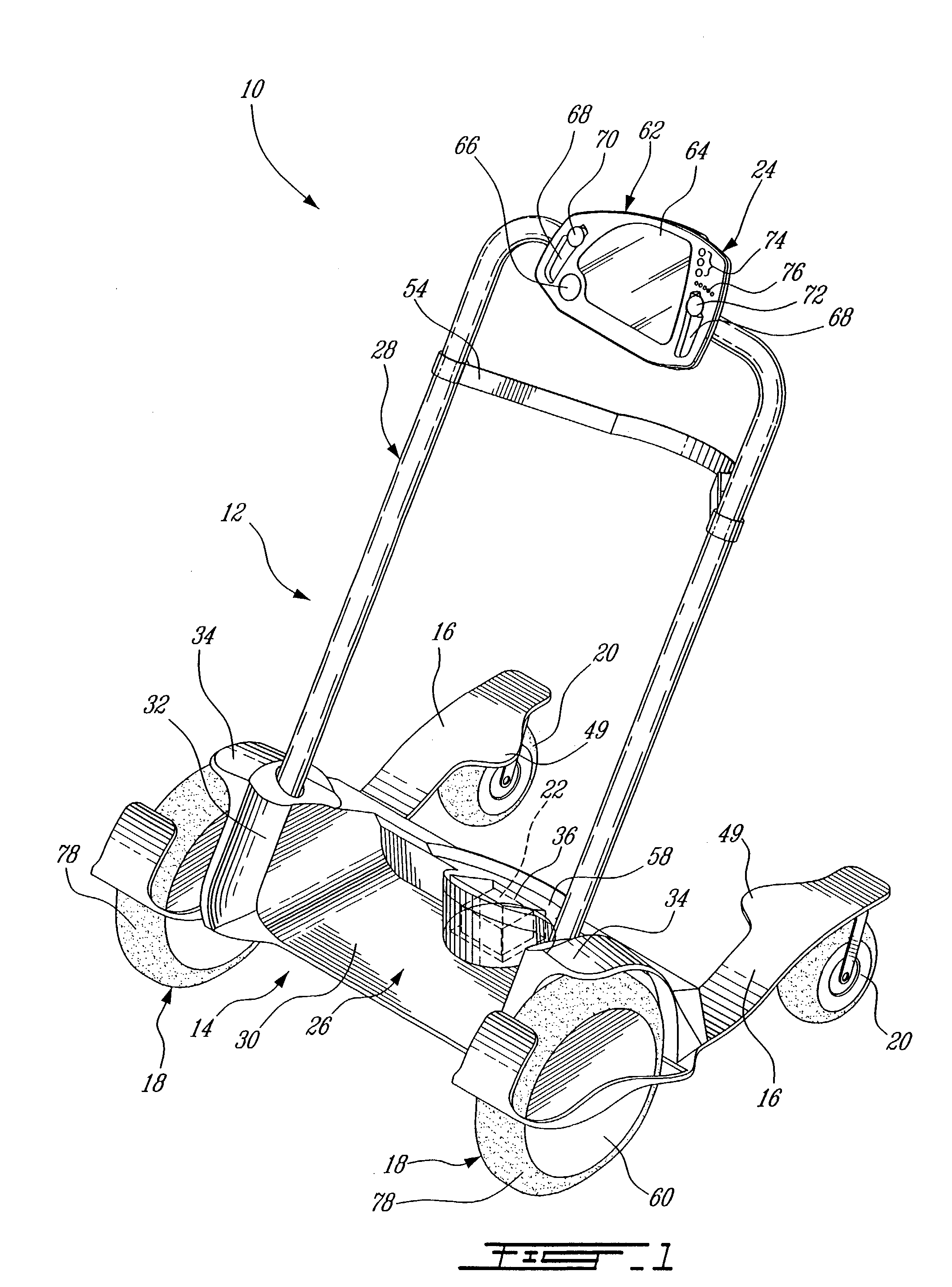
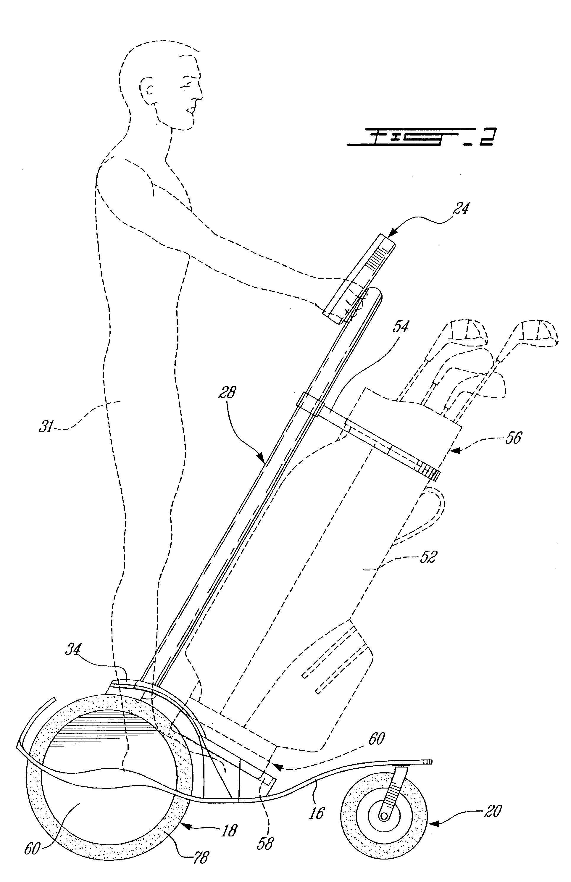
[0029]Turning now to FIGS. 1 and 2, a personal golf cart 10 according to the present invention is illustrated.
[0030]The golf cart 10 comprises a frame assembly 12 including a passenger receiving structure 14 mounted on longitudinal blade-like suspension members 16, two driving wheels 18, two driven wheels 20, a battery 22, and a controller 24.
[0031]The passenger receiving structure 14 includes a base 26, and a mounting structure 28. The base 26 includes a generally flat portion 30 for receiving a passenger 31 standing on his feet, two opposite lateral mounting structure receiving portions 32, two mudguard portions 34, each secured to a respective mounting structure receiving portion 32 opposite the flat portion 30, and a battery receiving compartment 36 advantageously closed by an access door (not shown).
[0032]The frame assembly 12 can be made from a single piece or assembled from various components. The frame assembly 12 is preferably made of polymer, for example, by rotational mol...
second embodiment
[0079]Turning now to FIG. 4, a wheelchair 100 according to the present invention is illustrated.
[0080]The overall configuration of the wheelchair 100 is similar to the one of the golf cart 10. The wheelchair 100 comprises a frame assembly 102 including a passenger receiving structure 104 mounted on two longitudinal flat suspension members 106 (only one shown), two driving wheels 107, two driven wheels 109, a battery (not shown), and a controller (not shown). The passenger receiving structure 104 includes a mounting structure 108 secured to both suspension members 106 via a base 110.
[0081]The base 110 includes a generally flat portion (not shown) between two opposite lateral mounting structure receiving portions 112 (only one visible), and a battery receiving compartment (not shown) advantageously closed by an access door (also not shown).
[0082]The bottom portion of the base 110 is provided with two lateral suspension member receiving slots 114 (only one shown). The slots 114 are gen...
third embodiment
[0105]Turning now to FIG. 5 of the appended drawings, a wheelchair 200 according to a personal cart according to the present invention is illustrated. Since the wheelchair 200 is very similar to the wheelchair 100, only the differences, and more specifically the actuating means 202 of the wheelchair 200 will be described herein in more detail. The general configuration of the wheelchair 200 is therefore as described with reference to FIG. 4. However, the actuating means differ: the controller and battery are replaced by a pair of actuating means 202 (only one shown), and the driving wheels are no longer in the form of motor-wheels but as conventional wheels 206, each having a hub 208 rotatably mounting the wheel 206 to the base 210.
[0106]More specifically, the actuating means 202 comprises a pair of endless belts 212, each one mounted to a respective leg of the U-shaped mounting structure 108 through a pair of pulleys 214–216. The pulleys 214–216 are rotatably mounted respectively t...
PUM
 Abstract
Description
Claims
Application Information