Three-dimensional quasi-coplanar broadside microwave coupler

a microwave coupler and quasi-coplanar technology, applied in the field of microwave couplers, can solve the problems of limited coupling factor control, small design flexibility, and important and irreducible part of the mmic cos

Active Publication Date: 2006-08-08
SUMITOMO ELECTRIC DEVICE INNOVATIONS
View PDF29 Cites 33 Cited by
  • Summary
  • Abstract
  • Description
  • Claims
  • Application Information

AI Technical Summary

Problems solved by technology

Because of their large size such couplers are responsible of an important and irreducible part of the MMIC cost.
The proposed topology enables tight 3 dB coupling but requires optimization of the polyimide layer thickness between the two conductor strips and to the ground resulting in little design flexibility.
Moreover, the control of the coupling factor is limited and tight 3 dB coupling can only be achieved for a specific value of the ground plane to respective conductor strips ratio of the polyimide layer thickness.
Insertion loss is quite high in this case (˜2 dB) due to the presence of the ground plane close to the conductor strips.
However, because of the CPW nature of the lower line, the characteristic dimensions of the coupler are large and the lines are unlikely to be foldable in a meandering way.
For the broadside coupler proposed by M. Engels and R. H. Jansen, the ideal quadrature between the coupled and the direct port cannot be achieved and the phase imbalance deviates linearly with the frequency.
At millimeter-wave frequencies, the phase imbalance can be significant and strongly limit the use of such a broadside coupler.
However, this contributes to the degradation of the amplitude imbalance and compactness of the coupler.

Method used


Image

  • Three-dimensional quasi-coplanar broadside microwave coupler
  • Three-dimensional quasi-coplanar broadside microwave coupler
  • Three-dimensional quasi-coplanar broadside microwave coupler

Examples


Embodiment Construction

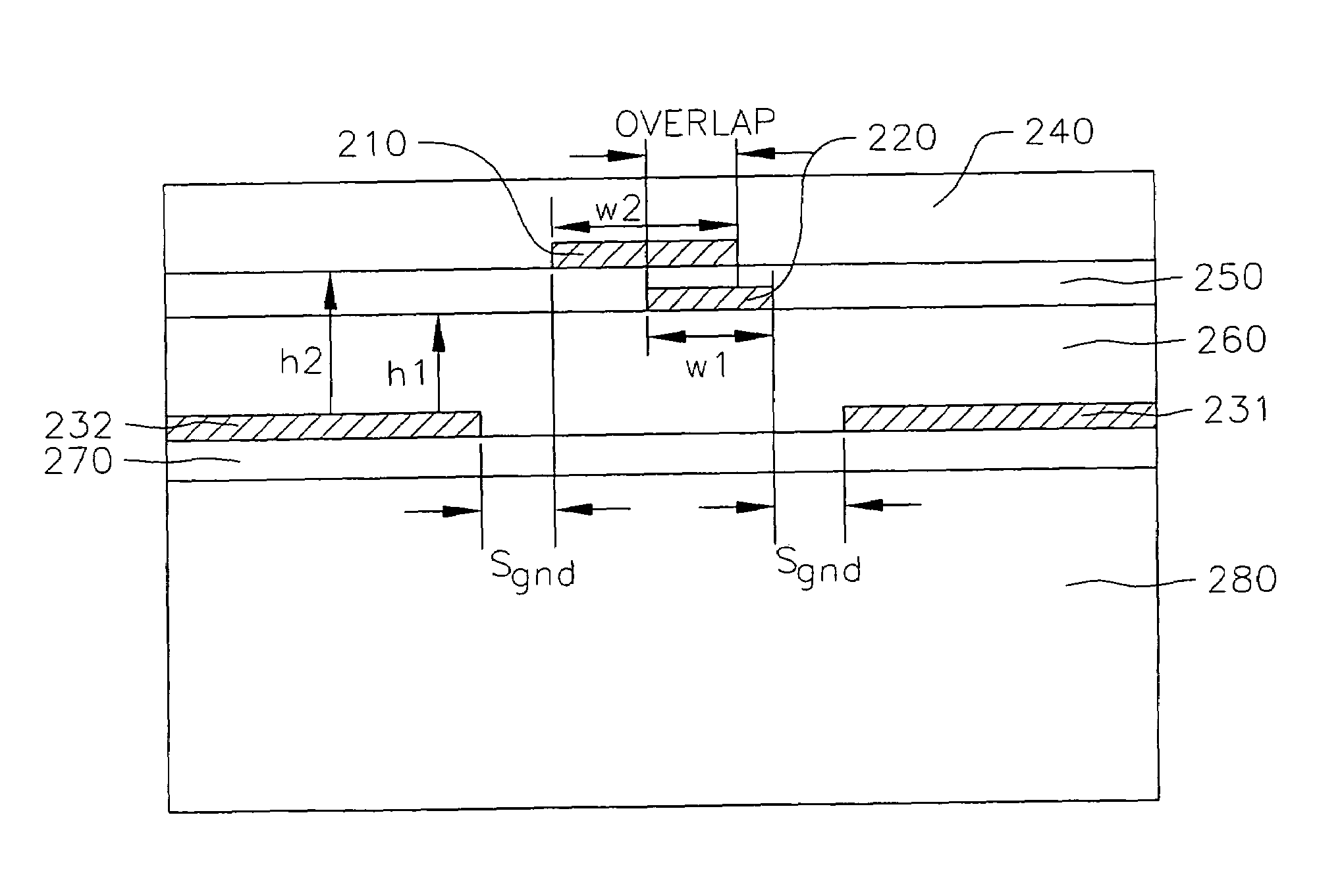
[0043]Referring now to FIG. 2, in accordance with the present invention a multi-layer coupler is provided composed of conductive material (e.g., metal) conductor strip 210 electro-magnetically coupled to conductive material conductor strip 220 both above conductive material ground plane 231, 232. Ground plane 231, 232 can be built on top of intermediate dielectric layer 270 formed over substrate 280 or be built directly over substrate 280 (e.g., dielectric layer 270 would not exist in this case). Intermediate dielectric layer 270 if inserted, enables the fabrication of active devices on substrate 280 and below ground plane 231, 232 without affecting coupler characteristics when used with MMIC technology.

[0044]Ground plane 231, 232 is placed below coupler conductor strips 210, 220 to shield the coupler performance from substrate 280 and any eventual active devices built on substrate 280. Therefore, the substrate thickness and properties have negligible effect on coupler performance a...


PUM


Abstract

A broadside 90° microwave coupler is composed of three metal layers in a homogeneous dielectric media. The coupler is constructed in a multi-layer configuration with two conductor strips arranged on top of each other so as to be electro-magnetically coupled. A ground plane formed with a third metal layer below the coupled conductor strips is opened so that it is separated from the conductor strips by a gap. The two conductor strips are fully embedded into the dielectric layer. The characteristic physical dimensions of the coupler are determined to achieve the desired coupling coefficient while maintaining low reflection, high isolation and phase balance at the output ports of the coupler.

Description

FIELD OF THE INVENTION[0001]The present invention relates to the field of microwave couplers and, more particularly, to millimeter-wave couplers fabricated with a multi-layer technology.BACKGROUND OF THE INVENTION[0002]90° tight 3 dB couplers are key components in monolithic microwave integrated circuit (MMIC) technology. They are commonly used in the design of frequency converters, balanced amplifiers and modulators. For planar microstrip MMICs, there are few alternatives and 90° couplers are generally implemented through the use of Lange couplers or Branch-line couplers. Because of their large size such couplers are responsible of an important and irreducible part of the MMIC cost.[0003]Recently, the introduction of the multi-layer or three-dimensional MMIC technology enabled the development of broadside couplers fabricated using transmission lines on top of each other and separated by a thin dielectric layer. Due to the multi-layer nature of broadside couplers, the thin film tran...

Claims


Application Information

Patent Timeline
Patent Type & Authority Patents(United States)
IPC IPC(8): H01P5/12H01P5/18
CPCH01P5/187
Inventor PIERNAS, BELINDA
Owner SUMITOMO ELECTRIC DEVICE INNOVATIONS
Why Eureka
Try Eureka