Shunt resistance and method of adjusting the shunt resistance
a resistance value and resistor technology, applied in the direction of resistor details, base element modifications, instruments, etc., can solve the problem of reducing the degree of design freedom, and achieve the effect of allowing the resistance value of the resistor to be easily adjusted
- Summary
- Abstract
- Description
- Claims
- Application Information
AI Technical Summary
Benefits of technology
Problems solved by technology
Method used
Image

Examples
embodiment 1
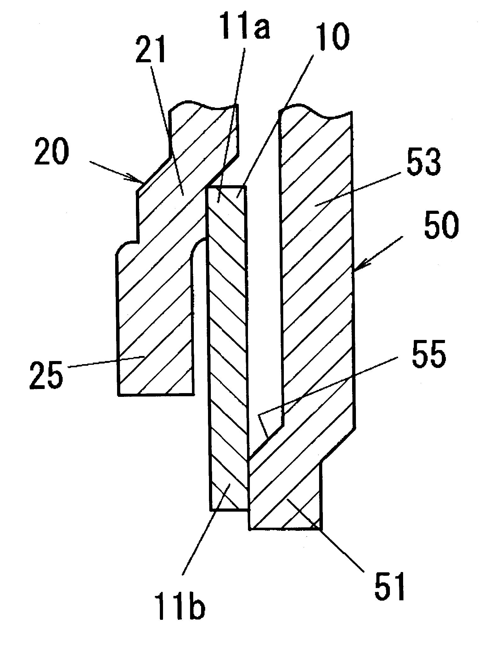
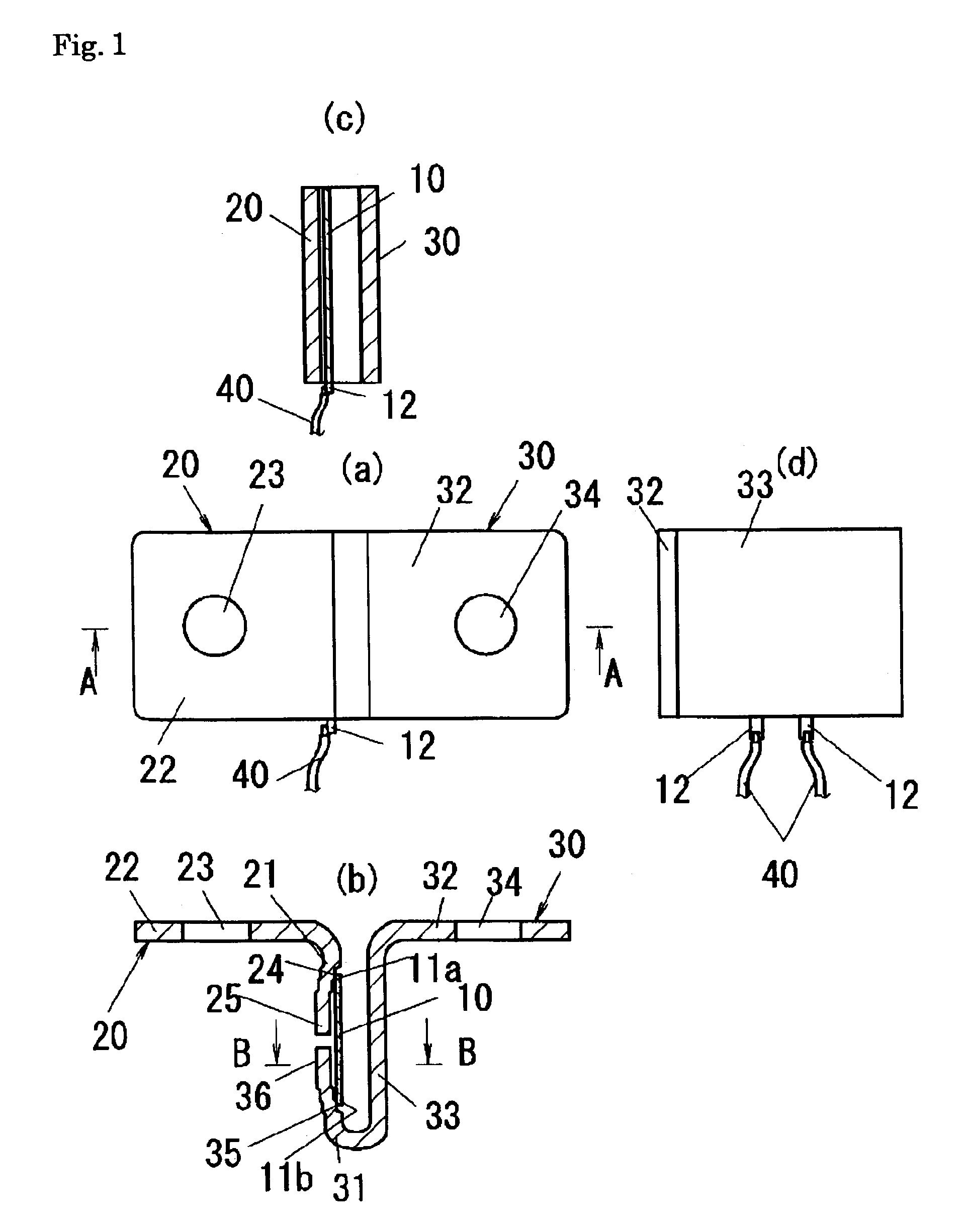
[0022]Hereinbelow, embodiment 1 of the invention will be described with reference to FIGS. 1 and 2. Referring to FIG. 1, a shunt resistor of the present embodiment includes a substantially planar resistor 10 having a predetermined resistance value; a first fixed terminal plate 20 that an end portion 21 on the one side is connected to one edge of the resistor 10; a second fixed terminal plate 30 that has an other-side end portion 31 which is connected to the opposing edge of the resistor 10, to have a portion in the vicinity of the end portion 31 which is bent substantially in the shape of the letter “U”, and to oppose the resistor 10 and at least a portion of the first fixed terminal plate 20; and a pair of lead wires 40 and 40 individually connected to the resistor 10 to take a voltage drop in the resistor 10 as a voltage signal.
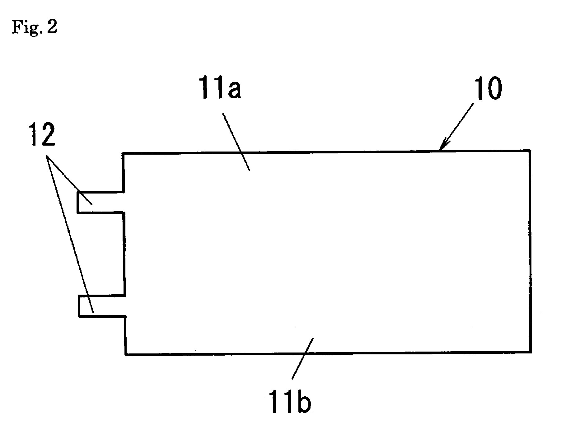
[0023]Referring to FIG. 2, the resistor 10 is formed of, for example, a copper-manganese alloy or a copper-nickel alloy, as a lengthy rectangular plate. Th...
embodiment 2
[0031]Hereinbelow, embodiment 2 of the present invention will be described with reference to FIGS. 5 and 6. The basic configuration of the present embodiment is common to embodiment 1 except for a second fixed terminal plate 50 having a different structure. The common configuration portions are designated by the same reference numerals / symbols, and descriptions thereof are omitted herefrom.
[0032]Referring to FIG. 5, in the second fixed terminal plate 50 of the present embodiment, a plate material made of an electroconductive metal material such as an electrolytic copper or an HSM (EF-TEC4) is bent substantially in the shape of the letter “L”, and a planar main portion 52 and a connection portion 53 that is substantially perpendicular to the main portion 52 are integrally formed. In addition, an end portion of the connection portion 53 is used as an end portion 51 that is connected to the resistor 10. Further, a circular insertion opening 54 is provided substantially in the center of...
embodiment 3
[0034]The basic configuration of the present embodiment is common to embodiment 2 except for a configuration in which a resistor 10 is positioned with respect to an end portion 21 of a first fixed terminal plate 20. The common configuration portions are designated by the same reference numerals / symbols, and descriptions thereof are omitted herefrom.
[0035]Referring to FIG. 7, in the present embodiment, instead of providing an indented portion 24, a protrusion 26 for positioning is provided on a face onto which the resistor 10 at the end portion 21 is connected. As shown in FIG. 7, the edge portion 11a of the resistor 10 is abutted on the protrusion 26 provided at the end portion 21, and the resistor 10 is thereby positioned to the end portion 21 of the first fixed terminal plate 20 and the connection position with respect to the end portion 21 of the resistor 10 can be stabilized.
[0036]Alternatively, as shown in FIG. 8, the configuration may be such that an engagement concave 13 enga...
PUM
 Abstract
Description
Claims
Application Information
 - R&D
- Intellectual Property
- Life Sciences
- Materials
- Tech Scout
- Unparalleled Data Quality
- Higher Quality Content
- 60% Fewer Hallucinations
Browse by: Latest US Patents, China's latest patents, Technical Efficacy Thesaurus, Application Domain, Technology Topic, Popular Technical Reports.
© 2025 PatSnap. All rights reserved.Legal|Privacy policy|Modern Slavery Act Transparency Statement|Sitemap|About US| Contact US: help@patsnap.com