
Apparatus to measure an amount of toner consumed and method thereof

a technology of toner consumption and measuring apparatus, which is applied in the direction of electrographic process apparatus, instruments, optics, etc., can solve the problems of increasing the manufacturing cost of the printer, unable to reflect the mainly variation of toner consumption, and the inability to ensure accurate measurement of toner consumption, so as to prevent errors in toner consumption measurement and increase the accuracy of toner consumption measuremen

Inactive Publication Date: 2006-08-08
S PRINTING SOLUTION CO LTD
View PDF9 Cites 12 Cited by
  • Summary
  • Abstract
  • Description
  • Claims
  • Application Information

AI Technical Summary

Benefits of technology

This approach provides accurate toner consumption measurement, preventing errors caused by varying image patterns and operation modes, and ensures precise toner exhaustion estimation.

Problems solved by technology

However, this approach requires a toner sensor and detection circuit, which subsequently increases a manufacturing cost of the printer.
Because it cannot be confirmed for sure that every page of the printing requires toner fixation for 4% to 5% of its area, accurate measurement of toner consumption cannot be guaranteed.
However, because this approach calculates toner consumption only based on the number of pixels of the counted printing data, by the Fringe effect, it cannot reflect the variations in toner consumption mainly according to varying modes of the operation such as print mode and a copy mode, and image patterns such as a solid pattern, a character pattern and a halftone pattern.
Therefore, accurate toner consumption measurement cannot be guaranteed.
However, this fourth suggestion requires software programs for the data processing in frequency reading, which subsequently increases the program loads.
Also, it has the possibility of errors in the software.

Method used


Image

  • Apparatus to measure an amount of toner consumed and method thereof
  • Apparatus to measure an amount of toner consumed and method thereof
  • Apparatus to measure an amount of toner consumed and method thereof

Examples


fourth embodiment

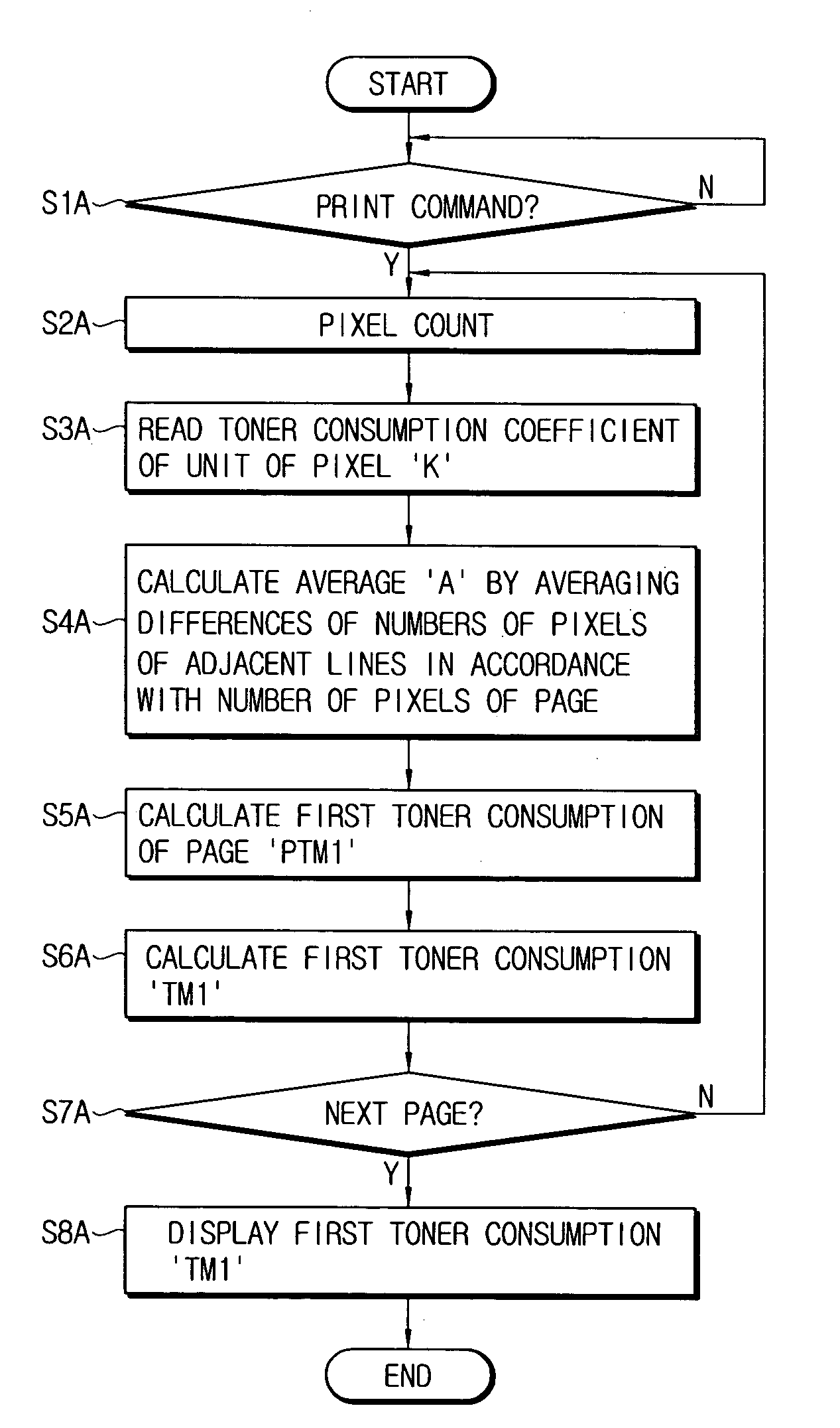
[0212]As described above, the toner consumption measuring apparatus 103″′ according to FIG. 10 uses, as a compensation coefficient to compensate for the toner consumption: i) the image pattern compensation coefficient ‘Kf’ corresponding to the image pattern which is determined according to the average ‘A’, or the average ‘A’ and the mode of the operation; and ii) the density compensation coefficient, which is determined according to the intended printing density, with the toner consumption being calculated according to the toner consumption coefficient of a unit of pixel ‘K’ and the number of pixels of a page. As a result, the present embodiment is particularly efficient in the prevention of errors in toner consumption measurement due to varying image pattern and printing density, and furthermore, can provide an estimate of toner consumption which is very close to the actual toner consumption.

[0213]The operation of the printing system 100″′ having the toner consumption measuring app...

fifth embodiment

[0224]The printing system 100″″ of the fifth embodiment is substantially similar to the printing system 100, 100′, 100″ and 100″′ illustrated in the embodiments of FIGS. 2, 6, 8, and 10, respectively, in terms of construction, and the only difference lies in the toner consumption measuring apparatus 103″″. Therefore, description of the like elements or structures will be omitted as much as possible for the sake of conciseness.

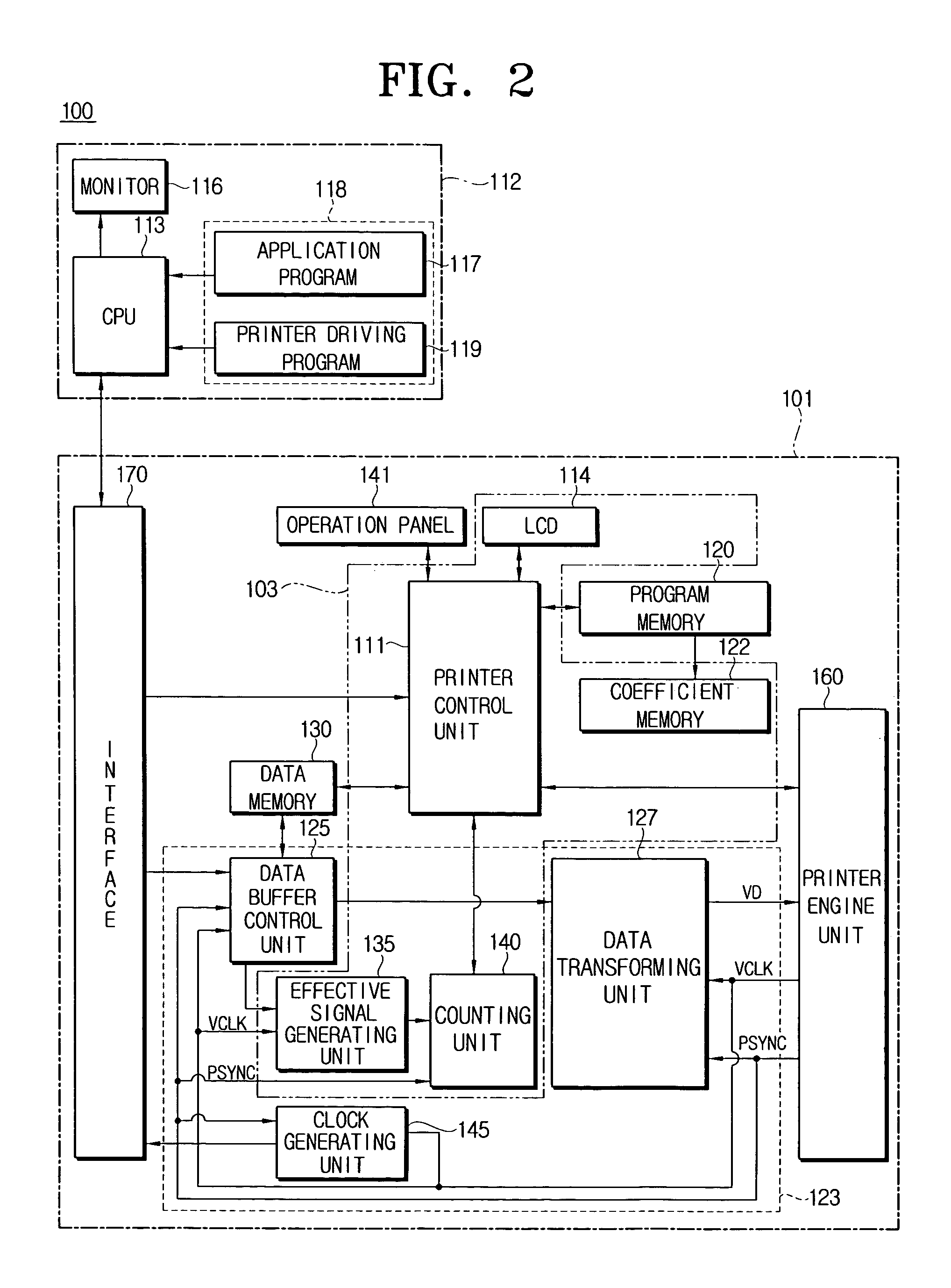
[0225]According to the embodiment of FIG. 12, the toner consumption measuring apparatus 103″″ may include an effective signal generating unit 135 such as an AND gate, a counting unit 140, a coefficient memory 122″″ installed in the program memory 120, and a printer control unit 111″″. The effective signal generating unit 135, such as an AND gate, receives inputs of printing data from the data buffer control unit 125 and the video clock signal ‘VCLK’ of the printer engine unit 160 for the synchronization of the printing data, and generates the data into binary i...


PUM


Abstract

A toner consumption measuring apparatus having an effective signal generating unit to receive inputs of printing data and a video clock signal to synchronize the printing data and to generate a count effective signal, a counting unit to count the generated count effective signal and to calculate a number of pixels of the printing data, a coefficient memory to store at least a toner consumption coefficient of a unit of pixel ‘K’ which is set in advance, and a printer control unit to determine an image pattern compensation coefficient by using the differences of numbers of the pixels of adjacent lines of a page in printing of every page, and calculating a toner consumption with applying a proper weight in accordance with the determined image pattern compensation coefficient.

Description

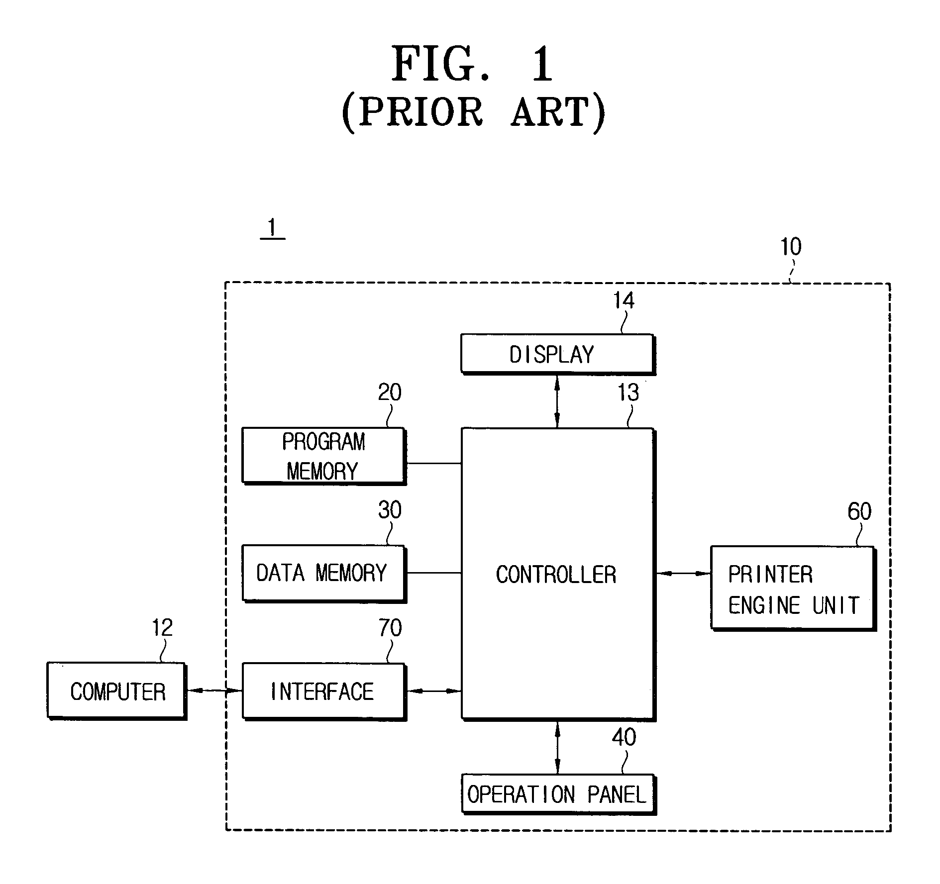
CROSS-REFERENCE TO RELATED APPLICATIONS[0001]This application claims the benefit of Korean Patent Application No. 2003-94443 filed Dec. 22, 2003, in the Korean Intellectual Property Office, the disclosure of which is incorporated herein by reference.BACKGROUND OF THE INVENTION[0002]1. Field of the Invention[0003]The present general inventive concept relates to an apparatus and a method thereof to measure an amount of toner consumed in a printing system which includes an image forming apparatus, and more particularly, to an apparatus and a method thereof to measure toner consumption in a printing system, which is capable of measuring the toner consumption by applying different weights in accordance with the varying operation mode and image pattern of the printing system.[0004]2. Description of the Related Art[0005]FIG. 1 shows a general structure of a conventional printing system 1. As shown, the conventional printing system 1 mainly comprises a laser beam printer 10 and a computer 1...

Claims


Application Information

Patent Timeline
Patent Type & Authority Patents(United States)
IPC IPC(8): G03G15/08G03G21/00
CPCG03G15/0856G03G2215/0888G03G15/556G03G15/08
Inventor AHN, DONG-CHEOL
Owner S PRINTING SOLUTION CO LTD
Learn More