Inter-system handover

a technology of inter-systems and handovers, applied in the direction of substation equipment, electrical equipment, wireless commuication services, etc., can solve the problems of affecting the service life the inability to meet the needs of customers, and the inability to meet the needs of the new network,

Inactive Publication Date: 2006-08-08
NOKIA TECHNOLOGLES OY
View PDF18 Cites 158 Cited by
  • Summary
  • Abstract
  • Description
  • Claims
  • Application Information

AI Technical Summary

Benefits of technology

[0018]The method preferably comprises a step of causing the further capability data to be transmitted in anticipation of a handover, suitably to allow the handover itself to be performed more quickly whilst reducing any need to unnecessarily transmit the further capability data. The method may comprise the step of monitoring at least one condition indicative of a need for the said handover, and initiating the said transmission by the user terminal of the further capability data when the said condition is beyond a threshold. The said condition is suitably based on the signal to interference ratio of the connection, although other factors may be used instead or in addition. The said step of initiating the said transmission by the user terminal of the first capability data is preferably performed when the said signal to interference ratio falls below the threshold. Alternatively, or in addition, handover may be anticipated when other events in the system occur, for example when the user terminal detects transmissions from a nearby access subsystem of another system to that to which it is connected. If the user terminal is a mobile station of a cellular telephone network then such a circumstance may arise when the mobile station starts to measure neighbour cells belonging to another type of radio access system than the one it currently communicates with.

Problems solved by technology

When a new cellular network is being introduced it can take some time to install all the base-stations and associated apparatus.
This presents a significant commercial problem for the operator of the new network.
If the new network is launched for use before its geographical coverage is complete then customers will be dissatisfied, by its inferior coverage to the old network.
However, the cost of the infrastructure of the new network is high and no return can be gained on it until it is in use.
However, the differences in the treatment of classmarks between the GSM and UMTS systems presents a significant barrier to inter-system handover.
However, this would increase signalling load unnecessarily in cases when no inter-system handover is subsequently performed.

Method used


Image

  • Inter-system handover
  • Inter-system handover
  • Inter-system handover

Examples


Embodiment Construction

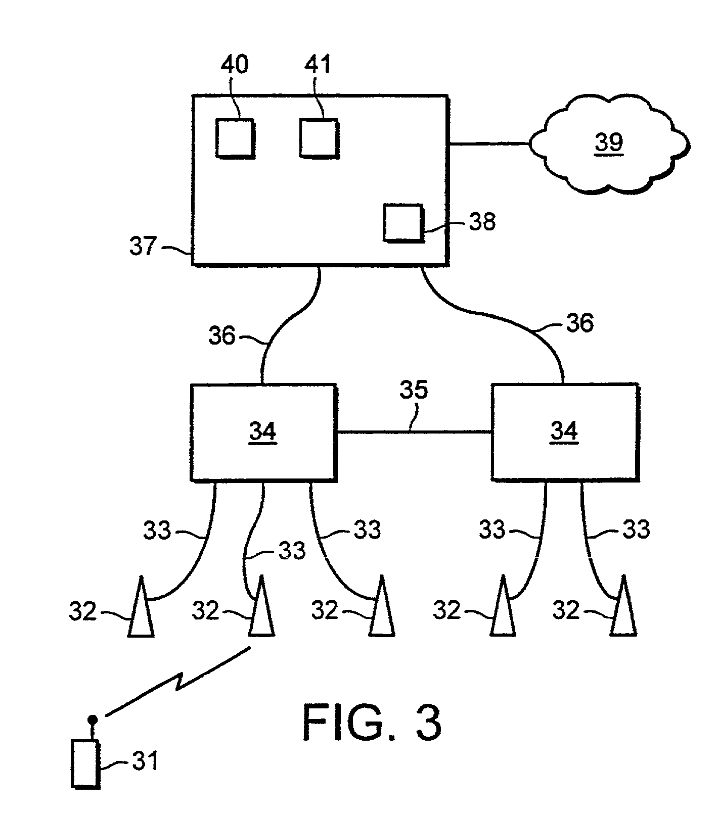
[0034]FIG. 3 shows generally the architecture proposed for UMTS. A mobile station (MS) 31 can communicate by radio with one or more base stations (BS) 32. Each base station is linked by an lub interface 33 to a single radio network controller (RNC) 34. Each RNC can be linked to one or more BSs. An RNC can be linked to another RNC by an lur interface 35. Each RNC is linked by an lu interface 36 to a core network (CN) 37. The CN includes one or more serving nodes that can provide communication services to a connected mobile station, for example a mobile switching centre (MSC) or a serving GPRS (general packet radio service) support node (SGSN)38. These units are connected by the lu interface to the RNCs. The CN is also connected to other telecommunications networks 39 such as fixed line networks or other mobile networks to allow onward connection of communications outside the UMTS network. The CN also includes other units such as a home location register (HLR) 40 and a visitor locatio...


PUM


Abstract

A method for performing an inter-system handover of a user terminal in a telecommunications network comprising a first telecommunications system operable according to a first protocol and comprising a first service subsystem and a first access subsystem and a second telecommunications system operable according to a second protocol and comprising a second service subsystem and a second access subsystem; the user terminal storing capability data indicative of the user terminal's capabilities for communication with the service subsystems and the access subsystems.

Description

PRIORITY CLAIM[0001]This is a national stage of PCT application No. PCT / IB00 / 01180, filed on Aug. 3, 2000. Priority is claimed on that application, and on patent application No. 9918636.3 filed in Great Britain on Aug. 6, 1999.FIELD OF THE INVENTION[0002]This invention relates to a method and apparatus for performing inter-system handover between telecommunications systems, and especially to the handling of classmarks or like indicators.BACKGROUND OF THE INVENTION[0003]In a mobile radio telecommunications system user's terminals communicate by radio with base stations which are connected to control units which control the operation of the mobile radio system and to the wider telecommunications network. The user terminal is often referred to as a mobile station (MS) which could be a mobile phone; however, the location of the MS could be fixed.[0004]FIG. 1 shows schematically the configuration of a typical cellular radio telecommunications network. The network comprises a number of ba...

Claims


Application Information

Patent Timeline
Patent Type & Authority Patents(United States)
IPC IPC(8): H04Q7/20H04W36/14
CPCH04W36/14H04W8/20
Inventor BACK, JUHAHULKKONEN, TONYVAINOLA, KATI
Owner NOKIA TECHNOLOGLES OY
Why Eureka
Try Eureka