Air mattress

Inactive Publication Date: 2006-08-15
THE COLEMAN CO INC
View PDF25 Cites 51 Cited by
  • Summary
  • Abstract
  • Description
  • Claims
  • Application Information

AI Technical Summary

Benefits of technology

[0011]The present invention provides an improved air mattress construc

Problems solved by technology

Although well adapted for their intended use as pool floats or as pool-side mattresses for sunning and the like, these first generation air mattresses did not perform as well in the role of bedding, a such.
Although this type of double height air mattress construction has provided increased comfort levels over single layer or height air mattresses, problems with these known types of mattress construction remain, chief among them being the inability to internally support the mattress so that any internal beams or columns used to form the mattress extend continuously from the bottom face to the top face of the mattress for more uniformly strengthening the mattress, and for more uniformly limiting the expansion or deflection of the mattress faces during use.
This is not possible with the known constructions as an intermediate sheet or layer of plastic material typically divides the two chambers or layers from one another.
Another problem

Method used


Image

  • Air mattress
  • Air mattress
  • Air mattress

Examples


Embodiment Construction

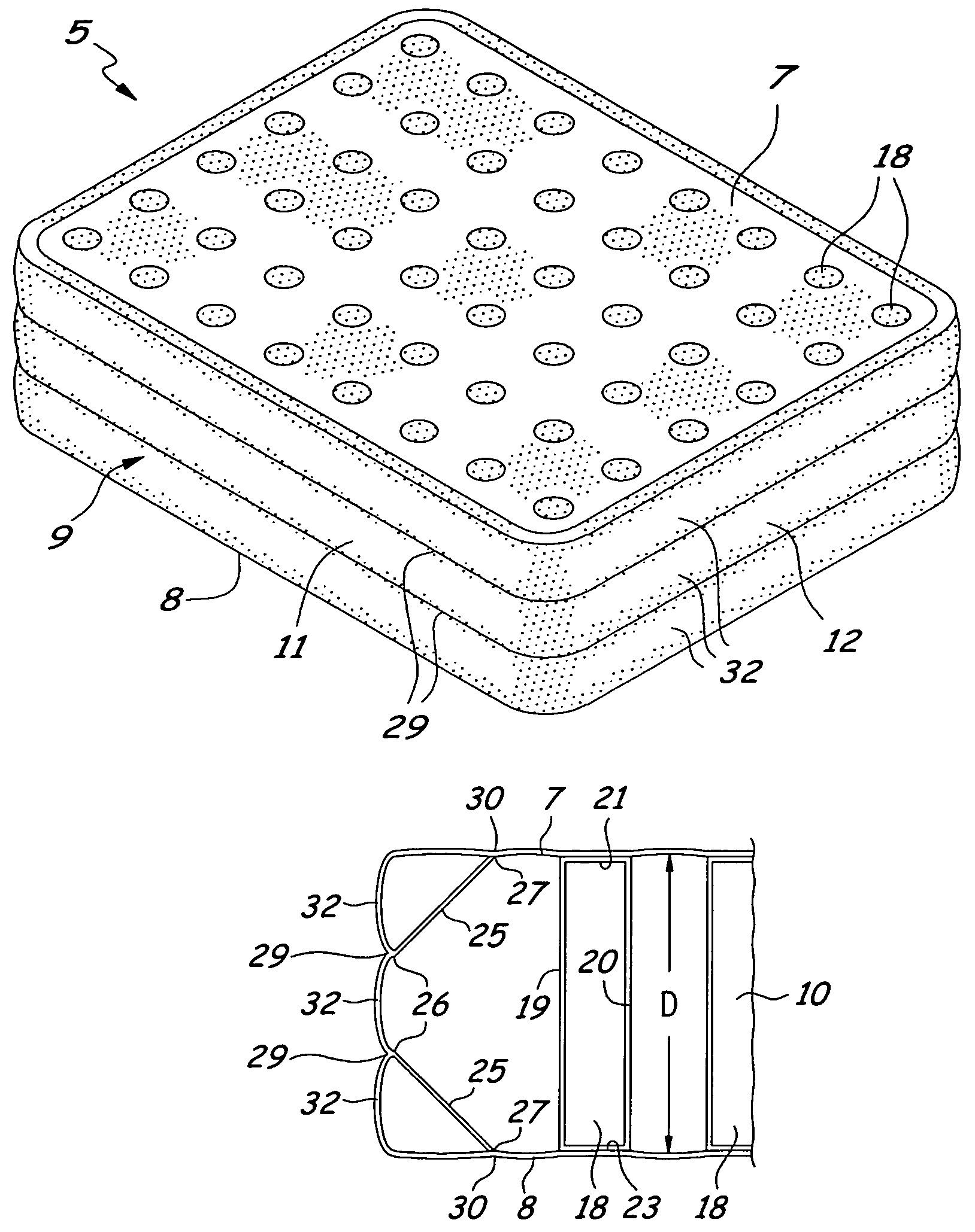
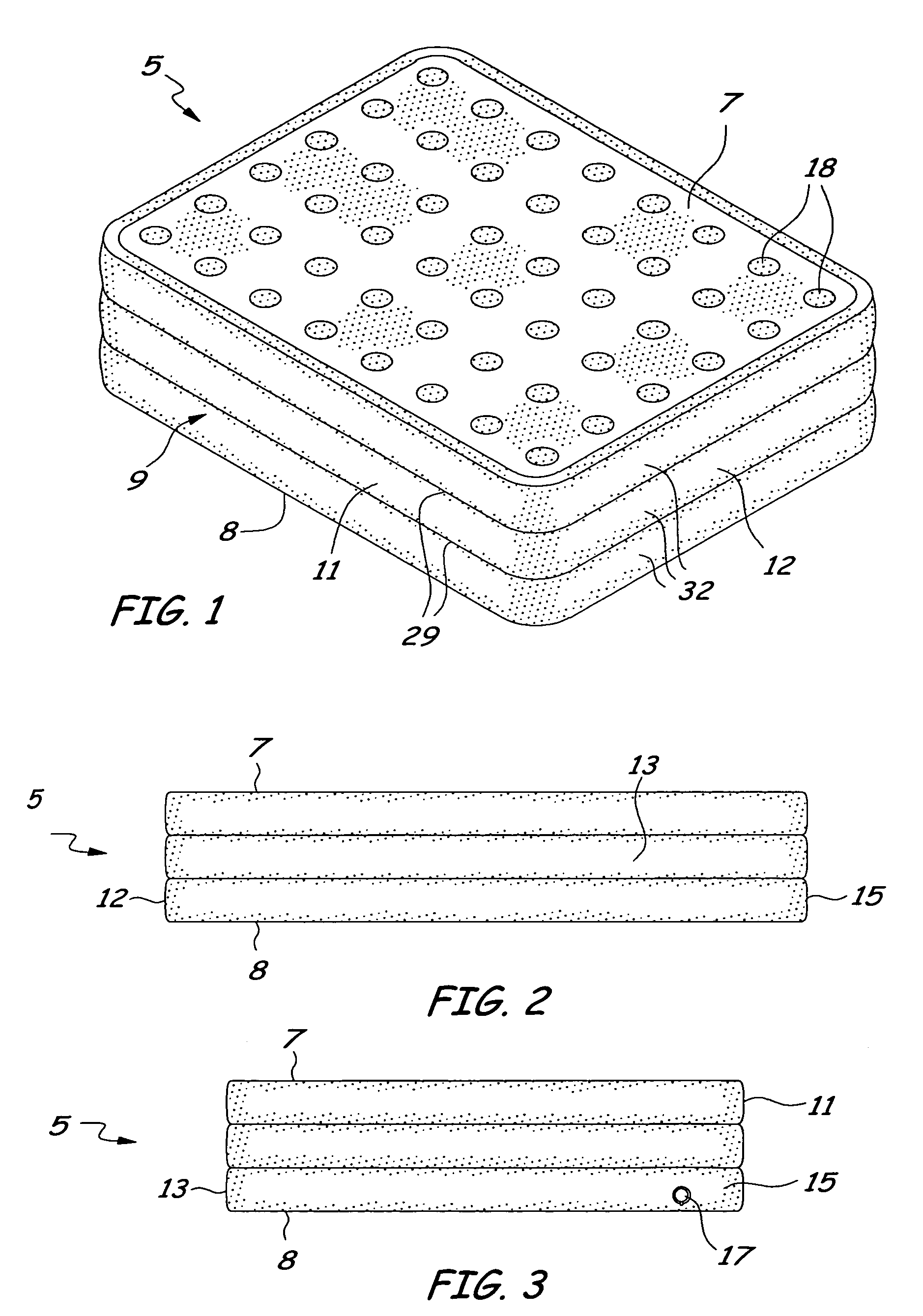
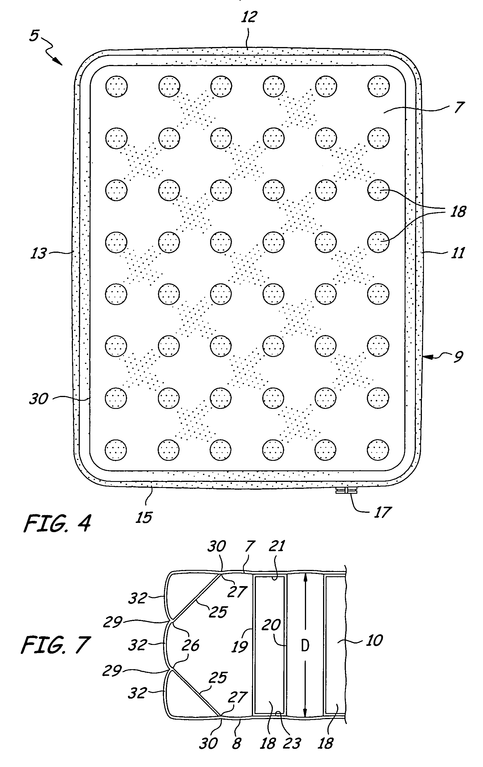
[0024]Referring now in detail to the drawings, in which like reference characters indicate like parts throughout the several views, an air mattress 5 of the invention is illustrated in FIGS. 1–4. The air mattress is formed of a first planar top panel 7 and a spaced second planar bottom panel 8 with at least one side panel or wall 9 extending between the first panel and the second panel. The at least one side panel, the first panel, and the second panel are conventionally joined to one another along their common peripheral side edges and together define an air chamber 10 within the boundary of the air mattress.

[0025]Still referring to FIGS. 1–4, the side panel of the air mattress may be formed of a first side panel 11, a second side panel 12, a third side panel 13, and a fourth side panel 15, each of which is joined to adjacent ones of the side panels, as well as to the first and second panels, respectively, of the mattress along their common peripheral side edges to once again defin...


PUM


Abstract

An air mattress or bed is disclosed. The air mattress has a first panel, a spaced second panel, and at least one side panel extending between the first panel and the second panel, each panel being joined to the other along their common peripheral edges to define a single air chamber therebetween. At least one mattress coil is disposed within the air chamber and is affixed to and extends therein from the first panel to the second panel. The air mattress further comprises at least one side support beam extending in the lengthwise direction of the at least one side panel. The side support beam has a first edge affixed to the at least one side panel and a spaced second edge affixed to at least one of the first panel and the second panel.

Description

FIELD OF THE INVENTION[0001]The invention relates in general to air mattresses or beds. More particularly, the present invention relates to an air mattress or bed constructed to limit the expansion or deformation of the mattress during use.BACKGROUND OF THE INVENTION[0002]The use of air mattresses or beds is well known. A great many types of air mattresses are known to exist, and are used widely for recreational purposes, for example as swimming pool floats, as well as for home use as a portable mattress or guest bed.[0003]As first developed and used, air mattresses were typically formed of a single layer or height reinforced internally by a spaced series of elongate beams, referred to by those skilled in the art as I-beams. These I-beams are typically extended in the lengthwise direction of the mattress and were secured to the top and bottom faces or panels of the mattress so that the mattress would hold its shape somewhat as a load, typically a person, was placed thereon. Although...

Claims


Application Information

Patent Timeline
IPC IPC(8): A47C27/08A47C27/045
CPCA47C15/006A47C27/087A47C27/081
Inventor METZGER, ANDREW T.
Owner THE COLEMAN CO INC
Why Eureka
Try Eureka