
Microfabricated vertical comb actuator using plastic deformation

Active Publication Date: 2006-08-15
RGT UNIV OF CALIFORNIA
View PDF6 Cites 20 Cited by
  • Summary
  • Abstract
  • Description
  • Claims
  • Application Information

AI Technical Summary

Problems solved by technology

From these applications, linkage- and hinge-designs have been identified as sources for reliability problems and for limitations on maximum frequencies of operation.
A limitation of the residual-stress method of fabrication is that the structure must be sufficiently flexible so that it undergoes appreciable deformation.
Designs that meet this requirement are generally limited in their ultimate operating frequencies to a few hundreds Hertz, Hz.
The challenging problems for the reflow of polymer hinges have been the control and reliability of the polymer material.

Method used


Image

  • Microfabricated vertical comb actuator using plastic deformation
  • Microfabricated vertical comb actuator using plastic deformation
  • Microfabricated vertical comb actuator using plastic deformation

Examples


Embodiment Construction

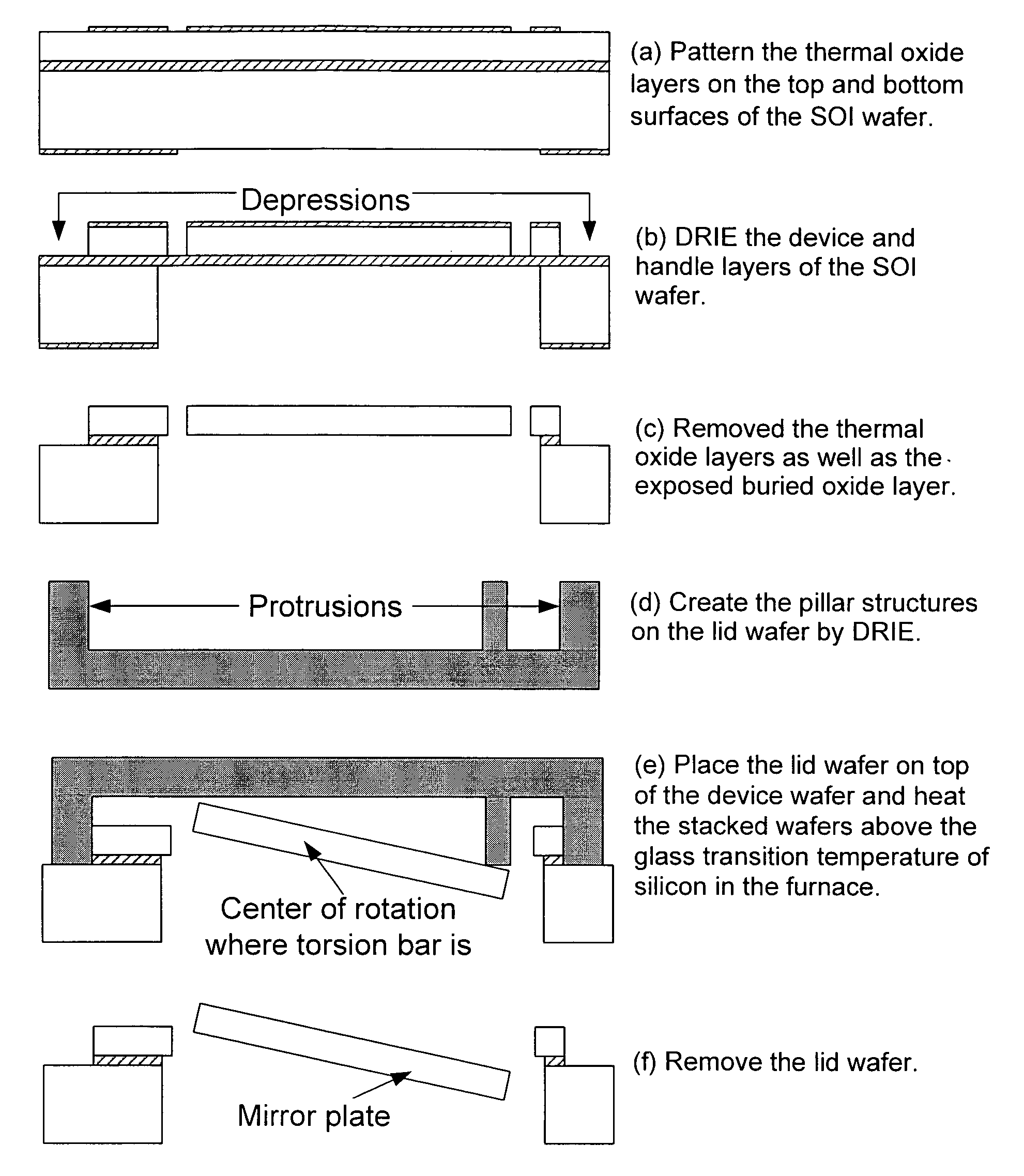
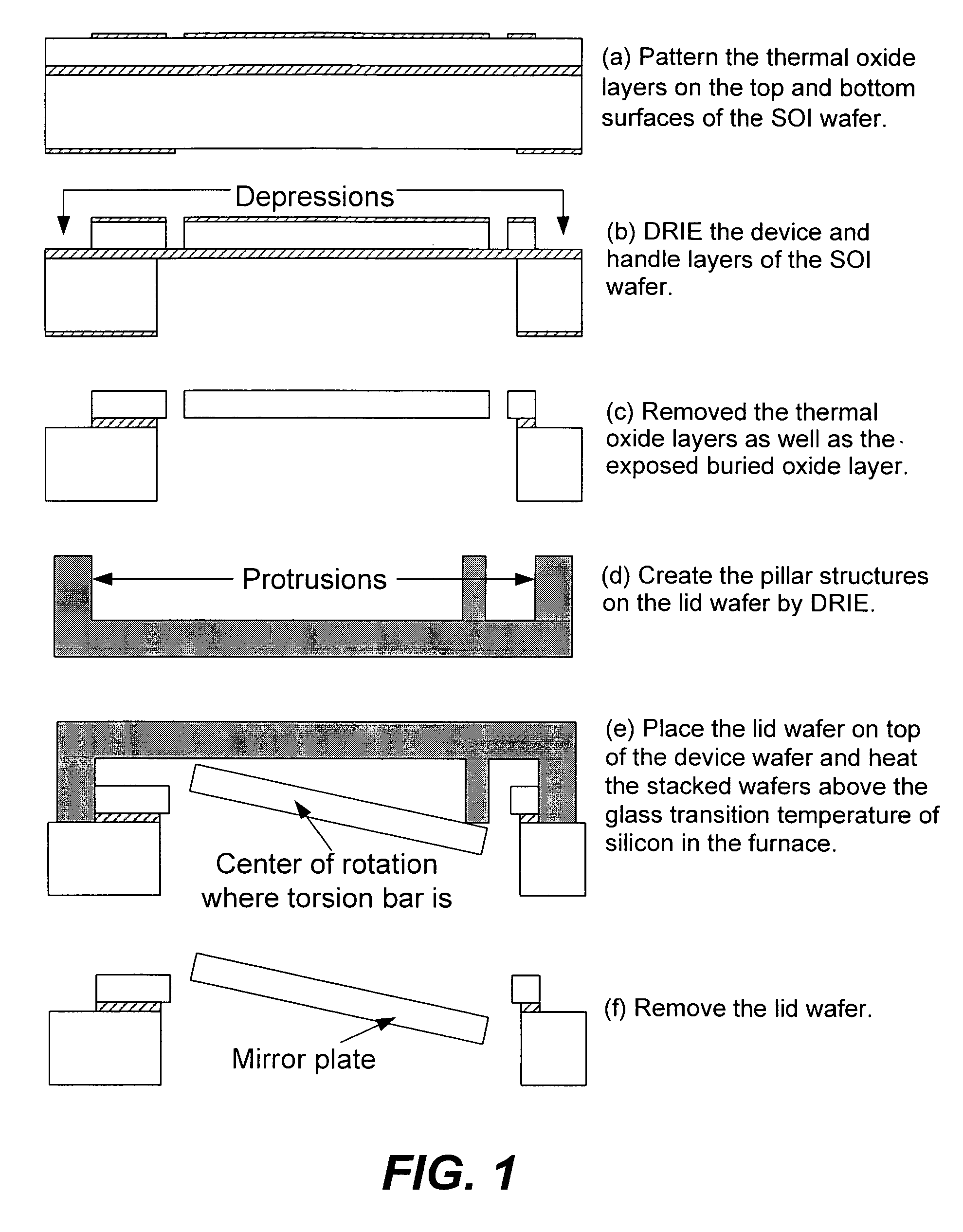
[0036]The design and fabrication of torsion-bar-supported scanning mirrors in accordance with the invention are demonstrated as an example of vertical-comb actuators made by the plastic-deformation process. FIG. 1 shows the new process. A torsion-bar-supported plate (which may, for example, function as a mirror) is formed in a first wafer. Using deep reactive ion etching, or DRIE, projecting pillars are configured in a second wafer and positioned such that, when the two wafers are stacked together, the projecting pillars push on and depress the mirrors on the first wafer. The two stacked wafers are annealed at temperatures greater than 800° C. causing the torsion bar to be plastically strained so that, after cooling to room temperature and separating the two wafers, the mirrors are permanently tilted from their original planar positions.

[0037]To start the process, the top- and bottom-combs and mirror plates are initially defined on the same device layer of an SOI wafer in FIGS. 1 (a...


PUM

PropertyMeasurementUnit
Plasticityaaaaaaaaaa
Electrical currentaaaaaaaaaa

Abstract

A microfabricated actuator of the vertical comb-drive (AVC) type or staggered vertical comb-drive type for torsional or linear applications includes torsion springs which permit self-aligned deformation of the device (micromirror) structure of the actuator through the heating of the torsional springs to plasticity. The torsional springs can include perpendicular-beam springs or double folded beams which allow axial movement of the spring when heated. Heating of the springs can be by bulk heating of the actuator structure or by Joule heating to the torsional springs by passing an electrical current therethrough.

Description

CROSS-REFERENCE TO RELATED APPLICATIONS[0001]This patent application claims the benefit of U.S. Provisional Patent Application Ser. No. 60 / 476,534, filed Jun. 6, 2003, which is incorporated herein by reference for all purposes.[0002]This application is related to copending application Ser. No. 60 / 570,021, filed May 10, 2004, which is incorporated by reference for all purposes.STATEMENT REGARDING FEDERALLY SPONSORED RESEARCH OR DEVELOPMENT[0003]This invention was made with Government funding under Grant (Contract) No. ECS0096098 awarded by the National Science Foundation. The Government has certain rights to this invention.BACKGROUND OF THE INVENTION[0004]This invention relates generally to microelectromechanical systems (MEMS), and more particularly the invention relates to torsional and linear vertical comb MEMS actuators and to the microfabrication of the actuator.[0005]Electrostatic comb-drive actuators are used in numerous MEMS applications where they have demonstrated their cap...

Claims


Application Information

Patent Timeline
IPC IPC(8): G02B26/00H02N1/00G02B26/08
CPCG02B26/0841H02N1/008Y10T29/49861Y10T29/49865Y10T29/49609
Inventor KIM, JONGBAEGLIN, LIWEI
Owner RGT UNIV OF CALIFORNIA
Learn More