Channelized stratified regenerator system and method

a stratified and regenerator technology, applied in the field of engine and coolers, can solve the problems of reducing long-term reliability, requiring extensive highly trained labor for the manufacture of conventional regenerators, and reducing the reliability of conventional regenerators

Inactive Publication Date: 2006-08-15
QNERGY
View PDF9 Cites 16 Cited by
  • Summary
  • Abstract
  • Description
  • Claims
  • Application Information

AI Technical Summary

Benefits of technology

[0013]Other aspects include the regenerator having a plurality of looping fins, and a plurality of spacers coupled to the looping fins to position and concentrically space apart the looping fins from one another to form concentric channels, therebetween, the spacers being positioned within the Stirling cycle based system to direct at least partial passage of the working fluid through the concentric channels between the first heat exchanger and the second heat exchanger along a pathway other than along the first dimension to cause the working fluid to travel a longer distance in going between the first heat exchanger and the second heat exchanger than it would if the working fluid would travel entirely along the first dimension between the first heat exchanger and the second heat exchanger. In some implementations the looping fins are rings.
[0014]Other aspects include the regenerator having a plurality of looping fins, and a plurality of spacers coupled to the looping fins to position and concentrically space apart the looping fins from one another to form concentric channels, therebetween, the spacers shaped to at least partially twist about the first dimension and positioned within the Stirling cycle based system to direct within the concentric channels at least partial passage of the working fluid between the first heat exchanger and the second heat exchanger along a pathway at least partially twisting about the first dimension to cause the working fluid to travel a longer distance in going between the first heat exchanger and the second heat exchanger than it would if the working fluid would travel entirely along the first dimension between the first heat exchanger and the second heat exchanger.
[0015]Other aspects include the regenerator having a cylindrical member centrally positioned within the regenerator along the first dimension, the cylindrical member having an exterior surface, and a plurality of fins extending radially from the exterior surface of the cylindrical member, the fins positioned and spaced apart from one another to form channels, therebetween, the channels being positioned within the Stirling cycle based system to direct at least partial passage of the working fluid between the first heat exchanger and the second heat exchanger along a pathway other than along the first dimension to cause the working fluid to travel a longer distance in going between the first heat exchanger and the second heat exchanger than it would if the working fluid would travel entirely along the first dimension between the first heat exchanger and the second heat exchanger.
[0017]Other aspects include the regenerator having a plurality of fin layers, each fin layer having a plurality of fins positioned and spaced apart from one another to form channels, therebetween, the channels being positioned within the Stirling cycle based system to direct at least partial passage of the working fluid between the first heat exchanger and the second heat exchanger; a first of the fin layers having a fewer number of fins than a second of the fin layers, and a plurality of diffusers, each of the diffusers having passageways, each of the diffusers positioned between a pair of the fin layers to align the passageways of the diffuser with the channels of the fin layers to direct flow of working fluid between the fin layers of the pair.

Problems solved by technology

Unfortunately, manufacture of conventional regenerators can demand extensive highly trained labor with many manufacturing steps.
Conventional regenerators can be difficult to integrate with other components of Stirling cycle engines or coolers, such as heat exchangers.
Another problem posed by conventional integration of regenerators with heat exchangers is that the regenerators are compressed fitted between the exchangers which adds more variableness to the final porosity of the regenerator both during time of assembly and also through the lifetime of operation.
As the conventional regenerator ages, the amount of compression placed upon the regenerator by its fitting between the two heat exchangers can change, which diminishes long term reliability.
In some cases compression lessens to a degree in which the regenerators become loose enough to vibrate and oscillate, which can result in shedding of small unwanted particles and subsequent machinery failure.
The random fiber mesh material used in the conventional regenerators is sintered which produces small particles that can migrate throughout the Stirling cycle engine or cooler potentially causing damage.
Construction of conventional regenerators provides little in the way of accurate control over either bulk or axial regenerator porosity of the random fiber mesh material.
Consequently, extensive operational testing is required to verify performance of conventional regenerators and undesirable amounts of costly scrap materials are produced.
Attempted remedies include some conventional regenerators using spaced apart foils, however, spacing between these foils is undesirably inconsistent and unpredictable.
Due to drawbacks of conventional regenerators and heat exchangers, reliability and performance of Stirling cycle engines and coolers suffers.

Method used


Image

  • Channelized stratified regenerator system and method
  • Channelized stratified regenerator system and method
  • Channelized stratified regenerator system and method

Examples


Embodiment Construction

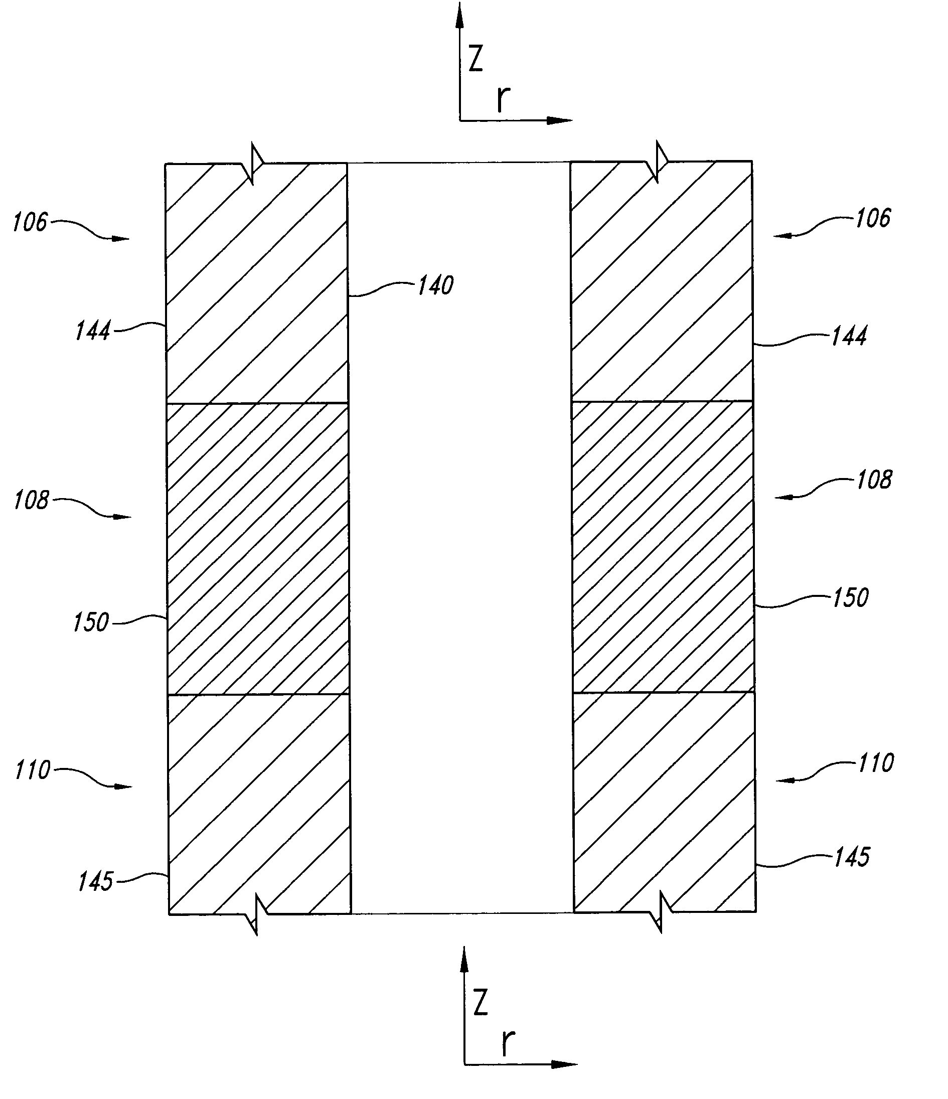
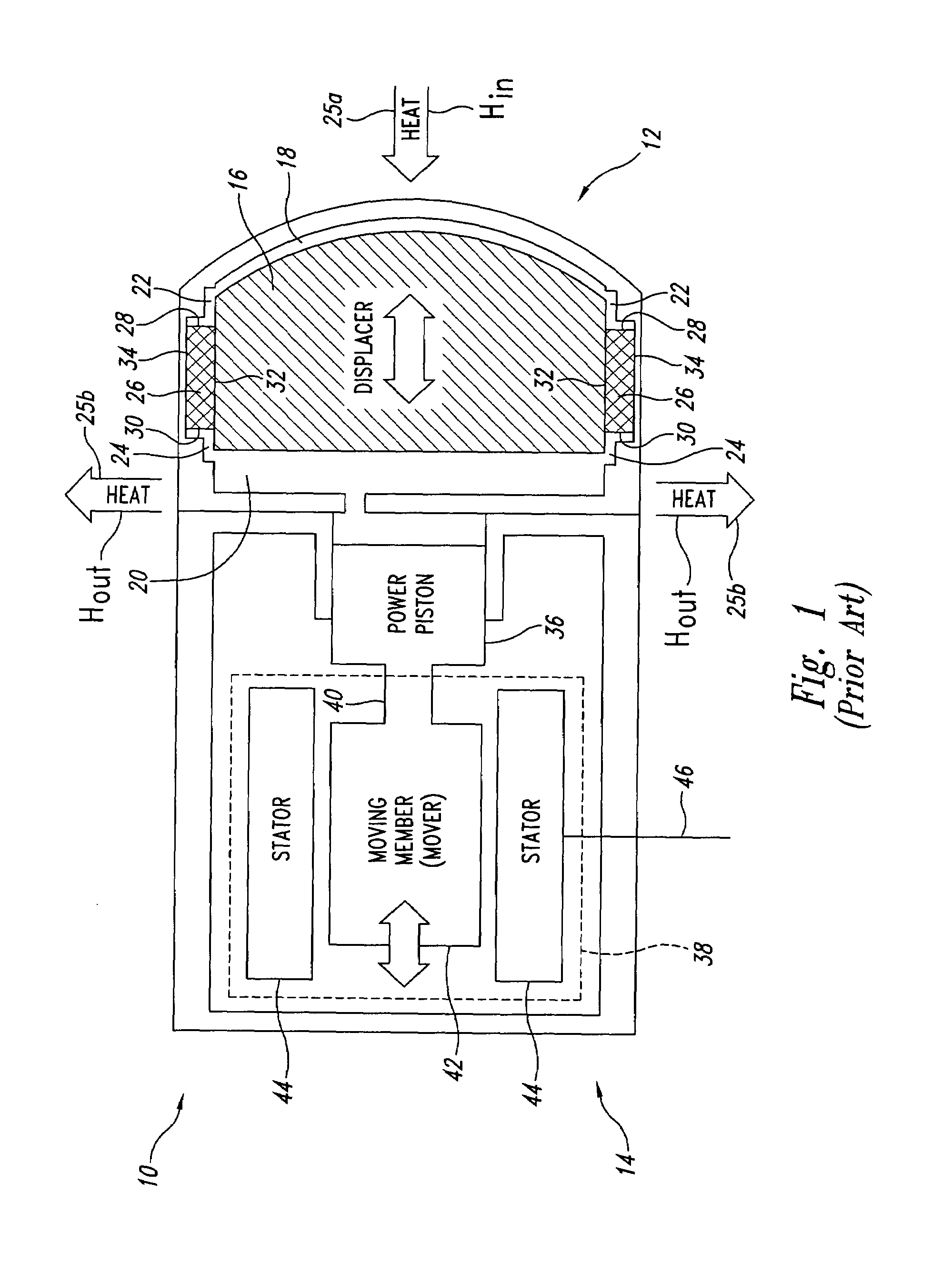
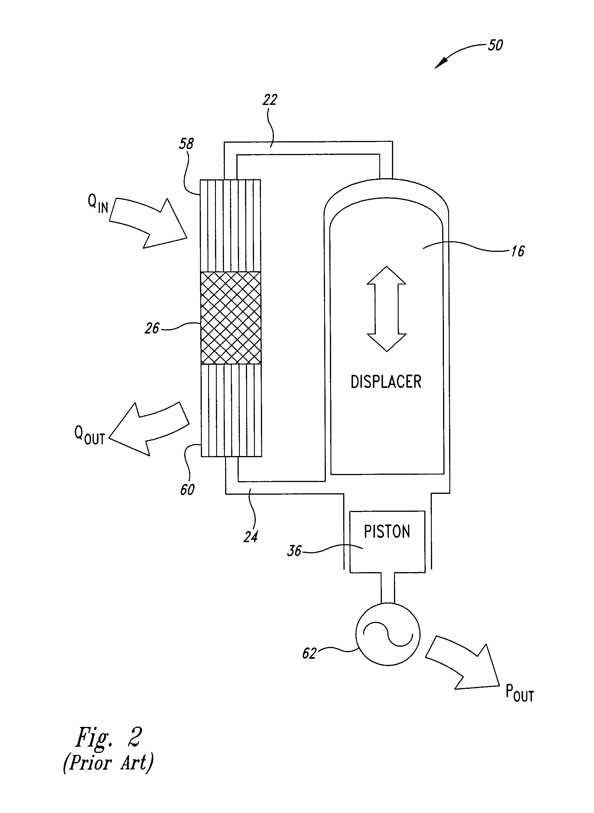
[0059]As will be discussed in greater detail herein, a channelized stratified regenerator with integrated heat exchangers system and method are disclosed using micromachining to precisely construct structural geometries and axial stratification of material. In operation, a working fluid passes through the regenerator when traveling between two heat exchangers. A first one of the two heat exchangers transfers heat from a heat source to the working fluid and a second one of the two heat exchangers transfers heat from the working fluid to a heat sink. With a Stirling cycle engine, the heat source can include chemical combustion, nuclear, solar, and other energy sources. Another heat exchanger can also be used to transfer heat from the energy source to the first heat exchanger. With a Stirling cycle cooler, a heat source is a room, device, or something else intended to be cooled. In some implementations, the heat sink can be another heat exchanger containing a coolant to carry heat off ...


PUM


Abstract

A channelized stratified regenerator with integrated heat exchangers are disclosed using micromachining to precisely construct structural geometries, such as fins and axial stratification of material to be used in a Stirling cycle based system. In operation, a working fluid passes through the regenerator when traveling between two heat exchangers. In some implementations, the regenerator and the heat exchangers are formed as a single construction. In other implementations, the regenerator and heat exchangers are formed separately, but are constructed to integrate efficiently with one another.

Description

BACKGROUND OF THE INVENTION[0001]1. Field of the Invention[0002]The present invention is directed generally to engines and coolers and, more particularly, to Stirling cycle engines and coolers.[0003]2. Description of the Related Art[0004]A conventional Stirling cycle engine or cooler includes a displacer moved by a working fluid, such as a gas. Portions of the working fluid travel in passageways between a hot area and a cold area. As the working fluid travels from the hot area to the cold area, it passes through a conventional random fiber mesh material called a regenerator that retains heat from the working fluid thereby lowering the temperature of the working fluid. As the working fluid returns from the cold area back to the hot area, it receives some heat back from the regenerator thereby resulting in increased efficiency. Unfortunately, manufacture of conventional regenerators can demand extensive highly trained labor with many manufacturing steps.[0005]Conventional regenerators...

Claims


Application Information

Patent Timeline
Patent Type & Authority Patents(United States)
IPC IPC(8): F01B29/10
CPCF02G1/057
Inventor QIU, SONGGANGAUGENBLICK, JOHN E.
Owner QNERGY
Why Eureka
Try Eureka