System and method for forming a non-rotationally symmetric portion of a workpiece

a technology of non-rotational symmetry and workpiece, applied in the direction of process and machine control, process control, instruments, etc., can solve the problems of excessive heat generation, vibration, and the use of fast tool servos, and achieve the effect of reducing the number of servos and generating the maximum number of servos

Active Publication Date: 2006-08-15
OMNIVISION TECH INC
View PDF5 Cites 20 Cited by
  • Summary
  • Abstract
  • Description
  • Claims
  • Application Information

AI Technical Summary

Benefits of technology

[0011]The present invention overcomes the obstacles associated with the use of fast tool servos to create an axis symmetric sphere or aspherical surface on a workpiece. The present invention is a slow tool servo having x- and z-axis linear slide drives and feedback systems as is typical of a conventional, axis symmetric, diamond turning and grinding...

Problems solved by technology

The utilization of fast tool servos, however, presents a number of problems.
Vibration is encountered with the rapidly moving parts of the fast tool servo, necessitating the need of dampening systems for attenuation of these vibrations.
The current used to actuate the piezo-electric crystals of the fast tool servo generates excessive heat.
This heat is created in the immediate area of the tool and affects the accuracy of the system.
It is not feasible to mount these spindles on a fast tool servo because of high inertia levels, and further because of their requirements for utilities such as electrical power, compressed air, and cooling water.
Another problem with fast tool servos is that the effective rake angle (the angle between the top of the tool and the workpiece surface) changes as a consequence of the changing circumferential slope of the axis asymmetric “potato chip” workpiece surface.
If, however, the changing rake angles are large, the cutting forces will change significan...

Method used


Image

  • System and method for forming a non-rotationally symmetric portion of a workpiece
  • System and method for forming a non-rotationally symmetric portion of a workpiece
  • System and method for forming a non-rotationally symmetric portion of a workpiece

Examples


Embodiment Construction

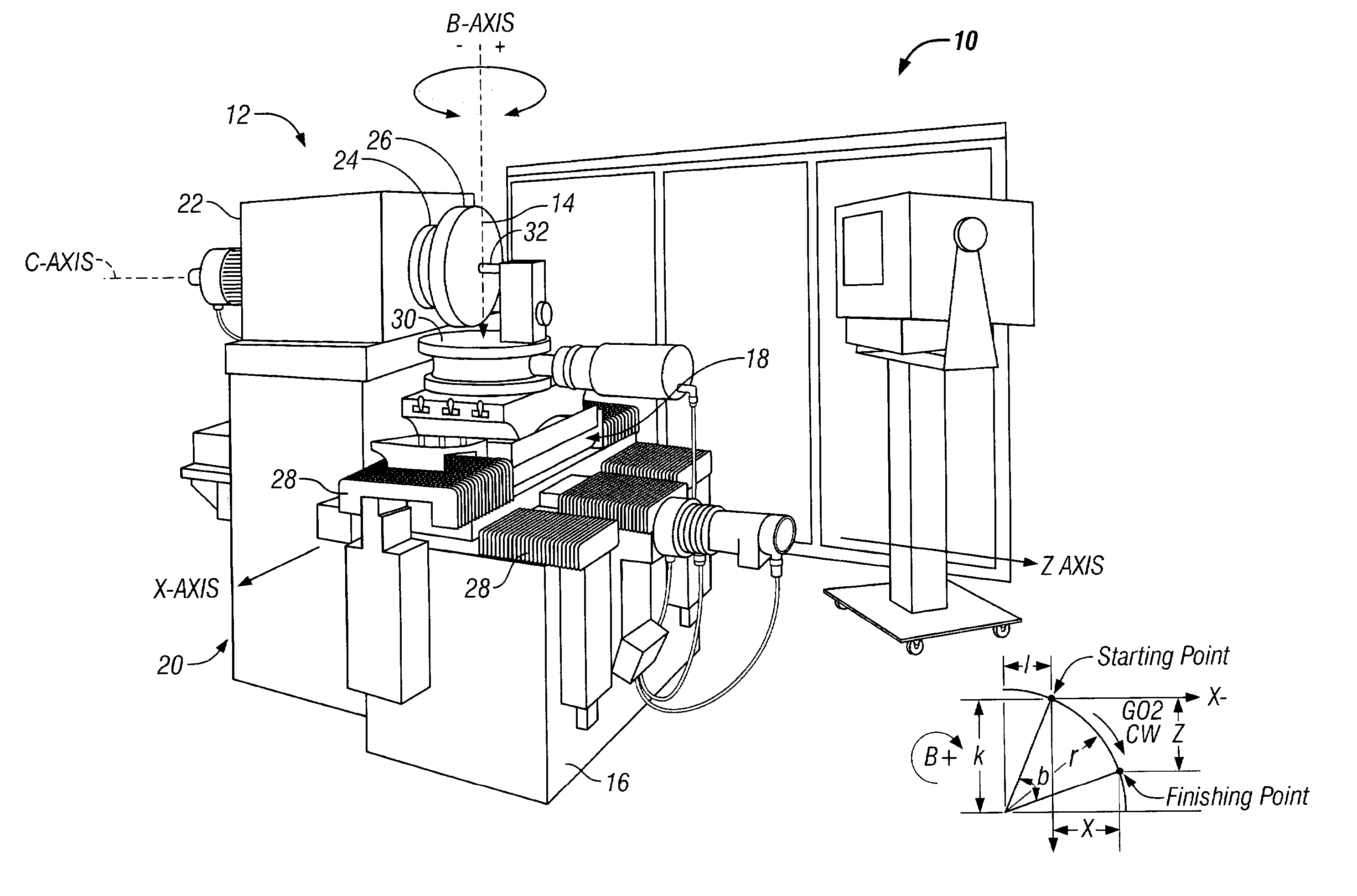
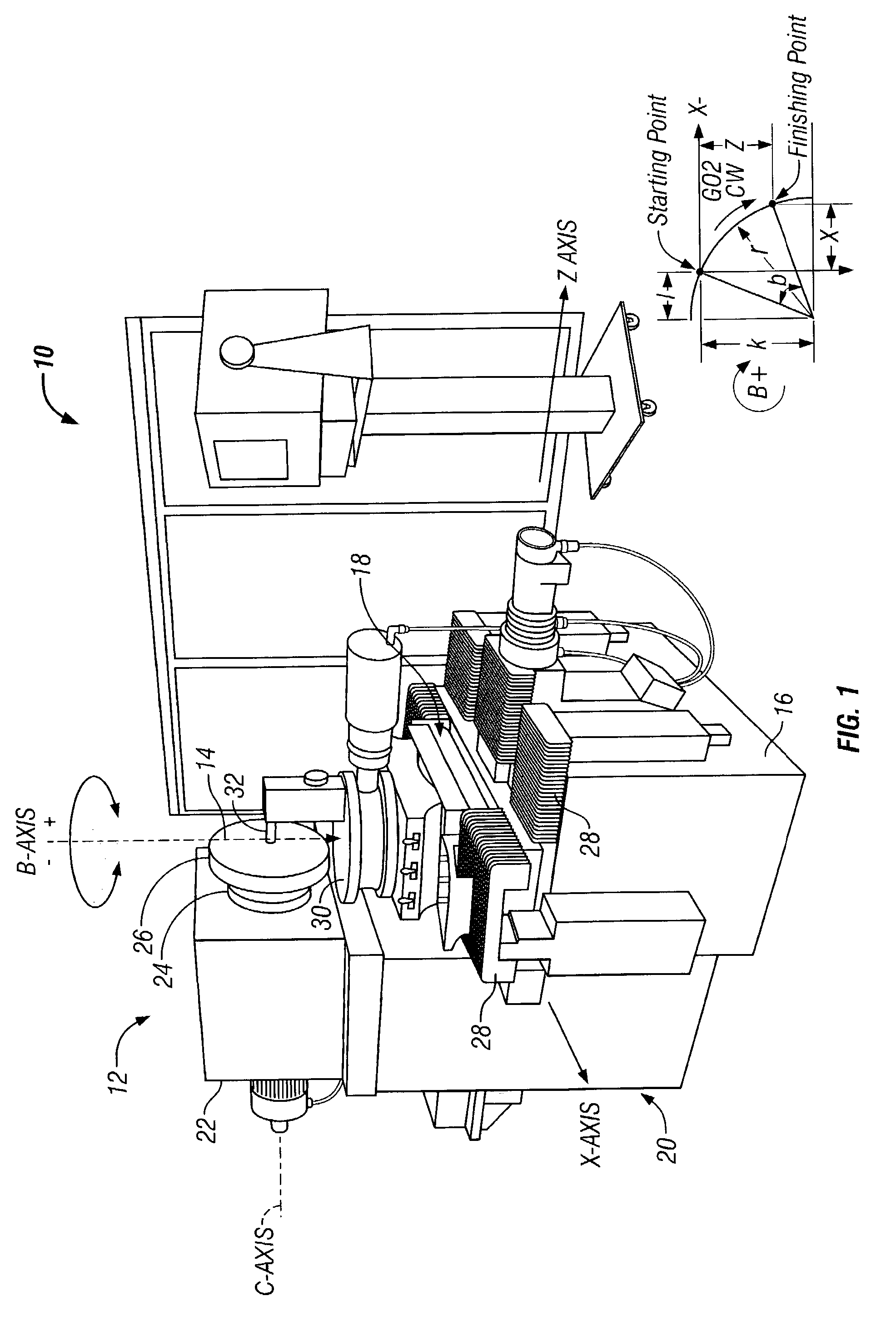
[0019]The system of the present invention is shown in use in FIG. 1 with an exemplary machine for forming shaped workpiece surfaces. The system 10 comprises a diamond turning or grinding machine 12 that is provided with associated programming instructions and controls to facilitate the fabrication of an axis asymmetric portion of a workpiece surface 14. The machine 12 generally has a base 16 upon which a platform 18 is slidably mounted and a spindle base 20 upon which a spindle assembly 22 is rotatably mounted. The spindle assembly 22 has a workpiece chuck 24, such as a vacuum chuck, for securely holding a workpiece 26 for rotation. Preferably, the chuck 24 rotates about a horizontal c-axis. The platform 18 of the machine is movable along linear slides 28 that extend along horizontal x- and z-axes orthogonal to one another, the z-axis being parallel to the c-axis. A table 30 is mounted to the platform 18 and one of a working tool 32 (e.g., a diamond cutting tool) or grinding spindle...


PUM

PropertyMeasurementUnit
Angleaaaaaaaaaa
Symmetric field theoryaaaaaaaaaa

Abstract

A method and control system for forming workpiece surfaces with at least a portion being non-rotationally symmetric (i.e., axis asymmetric) is provided. In one aspect, a slow tool servo system is provided to fabricate a surface having at least an axis asymmetric portion, and optionally, a superimposed axis symmetric asphere or spherical portion. A workpiece is mounted on a spindle and a tool is mounted to a translatable tabletop surface. The z position of the contact point of the workpiece and working tool is determined as a function of the x position of the same contact point and as a function of the angle of rotation of the spindle about the spindle axis. By making the z position of the contact point a function of both the angle of spindle rotation and the x position, the lateral and longitudinal position of the working tool can be moved at designated spindle rotation angles to form a surface having both axis asymmetric and axis symmetric asphere or spherical portions.

Description

RELATED APPLICATION[0001]This application is the nonprovisional application of provisional application Ser. No. 60 / 394,175, Jul. 3, 2002 entitled SYSTEM AND METHOD FOR FORMING A NON-ROTATIONALLY SYMMETRIC PORTION OF A WORKPIECE, the aforementioned application is incorporated herein by reference thereto.BACKGROUND OF THE INVENTION[0002]This invention relates generally to the machining of surfaces, and more particularly, to a method and apparatus for forming axis asymmetric workpiece surfaces.Description of the Related Art[0003]Machines for fabricating high-tolerance surfaces are known, such as lathes that utilize diamond turning and grinding tools. Typically, a workpiece made of a metal, glass, or synthetic material is secured in a chuck of a lathe spindle and brought into contact with a diamond cutting tool or grinding wheel (referred to hereinafter as a “tool”). A tool holder mounted on a tabletop surface, which is either stationary, rotatably mounted, or slidably mounted to a base...

Claims


Application Information

Patent Timeline
IPC IPC(8): B23B7/14B24B11/00B24B13/06B24B49/10
CPCB24B11/00B24B13/06B24B49/10Y10T82/16951Y10T82/2502Y10T82/10G05B2219/35116
Inventor BRYAN, JAMES B.
Owner OMNIVISION TECH INC
Why Eureka
Try Eureka