Face mask support
a technology for supporting masks and face masks, applied in breathing masks, breathing protection, respirators, etc., can solve problems such as fatigue or exhaustion, disruptive snoring, and decreased mental and physical performan
- Summary
- Abstract
- Description
- Claims
- Application Information
AI Technical Summary
Benefits of technology
Problems solved by technology
Method used
Image
Examples
example 1
First Embodiment
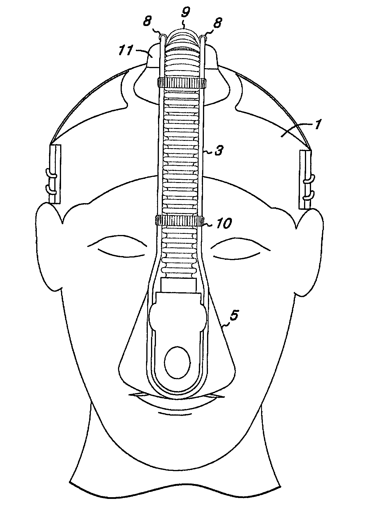
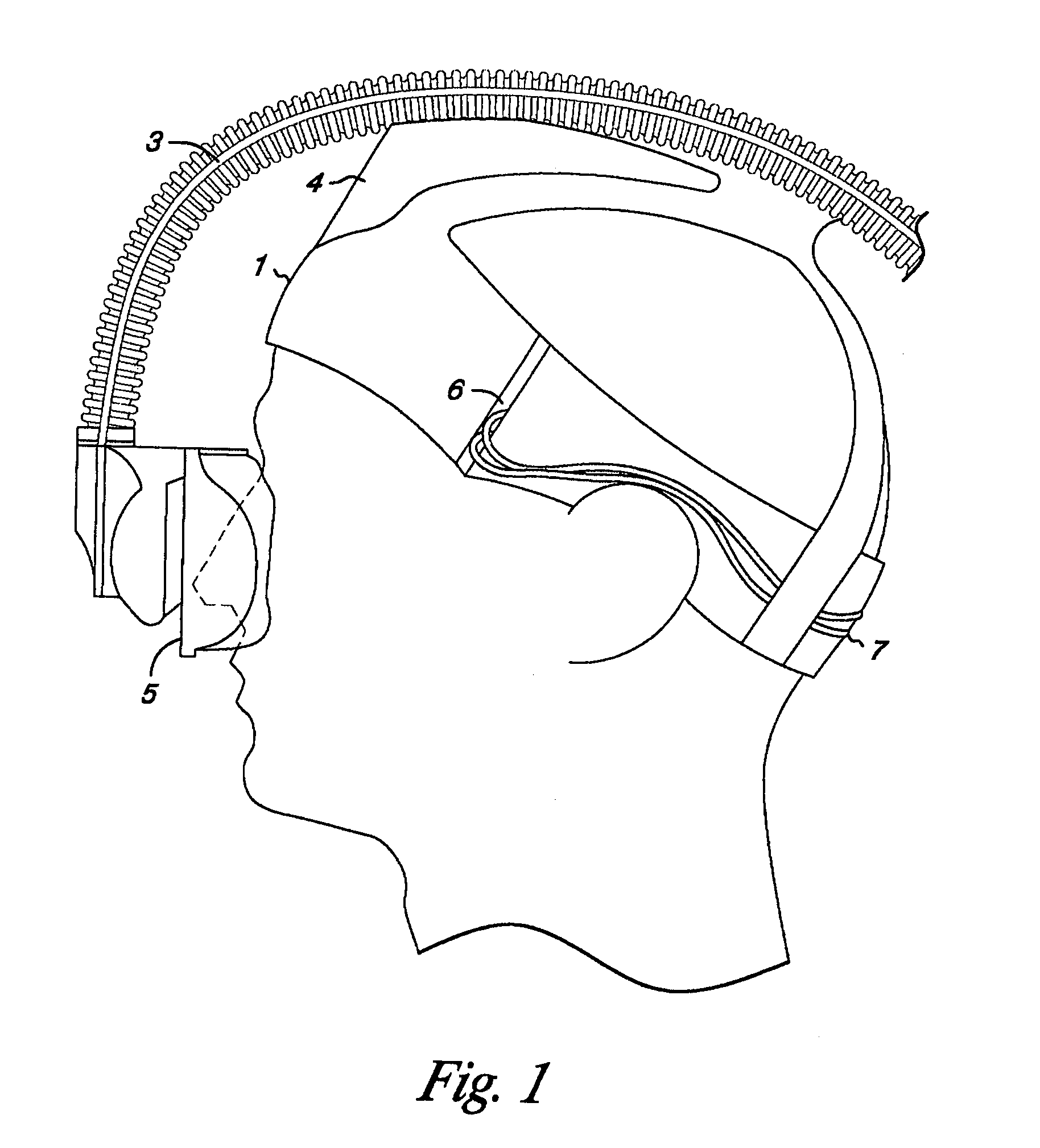
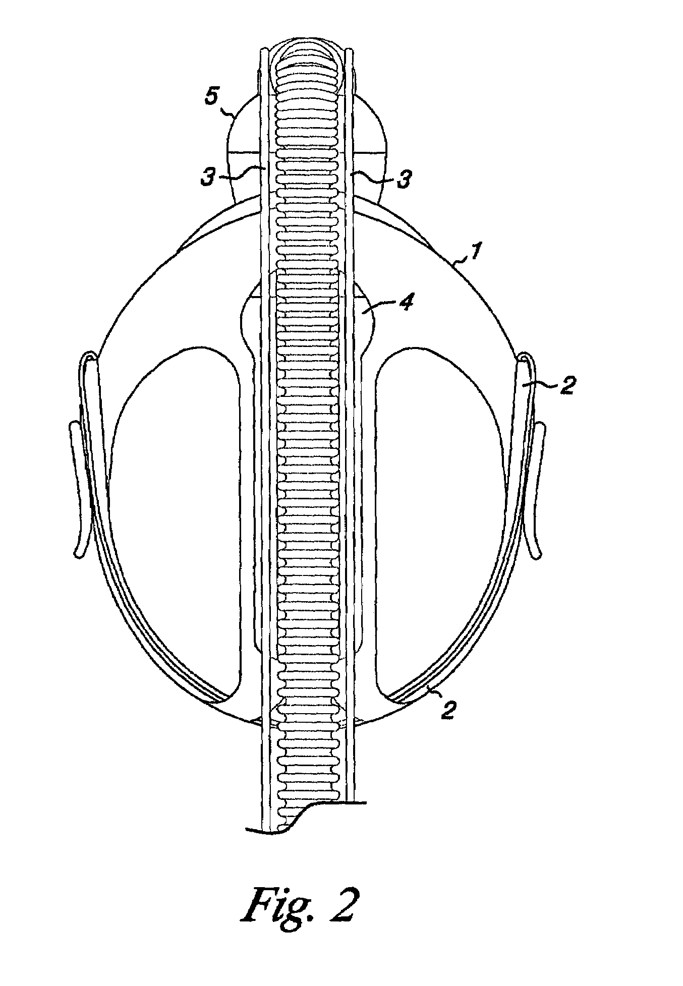
[0049]Looking at FIG. 1, the circumference edge 1 of the open cap is seen to extend from the middle of the forehead, avoiding the sensitive eye and eyebrow regions, to below the inion protrusion of the occipital bone (the nape of the neck). The circumferential edge of either the open cap or the closed cap describes a hemisphere. This natural positioning gives stability to the mask support cap, in that the nape, where the spine joins the head, is the “low point” of the head, to which any encircling band will incline to rest. Thus, the circumferential band replaces both the forehead and occipital anchor points that are commonly found on similar devices. (See, e.g., U.S. Pat. No. 6,515,802.) The circumferential band is maintained on the head with loading that is applied independent of the loading of the face seal, unlike the supports in U.S. Patent Application US 2002 / 0117177. The edge of the circumferential band 1 is joined at the forehead and the rear of the head to t...
example 2
Second Embodiment
[0061]The face mask support of Example 1 is comfortable and stable. Improvements to the design were sought to further reduce the weight and the area of contact with the patient's head to make a support that is even more comfortable, while retaining the clamping feature that provides stability shown in FIG. 4.
[0062]FIG. 5 shows a profile view of the invention with the circumferential band 18 encircling the head from the forehead just below the hair line to the inion protrusion of the occipital bone of a patient. The circumferential band in this embodiment is designed to sit higher on the forehead of the patient than in the first embodiment, causing the band to pass near on the ear. Therefore, an S-shaped curve at approximately the level of the ear prevents irritating contact with the ear. A stabilizing band 19 extends upward from approximately the area of the S-shaped curve to the crown of the head. A biasing means support 20 is positioned to extend from the circumfe...
example 3
Configurations of the Biasing Means
[0074]While the configuration of the biasing means as shown in FIGS. 5 to 9 is ideal, the biasing means may be varied. FIG. 10 shows a biasing means 23 with two descending arms inserting into the receiving slots 27A and 27B on the biasing means support 20. The arms are joined into a single descending arm which inserts into a plenum.
[0075]FIG. 11 shows a biasing means support 20 with a single receiving slot 27 for a single-armed biasing means.
[0076]FIG. 12 shows a biasing means inserted through receiving slots 27A and 27B to the biasing means support 20. Each arm is inserted directly into a plenum rather than supporting the plenum by forming a surrounding loop. The bands 37 provide stability.
[0077]FIG. 13 shows a double biasing means support 20 A and 20B where each arm of the biasing means 23 inserts into a separate biasing means support through receiving slots 27A and 27B.
[0078]FIG. 14 shows a biasing means that is constructed of two separate piece...
PUM
 Abstract
Description
Claims
Application Information
 - R&D
- Intellectual Property
- Life Sciences
- Materials
- Tech Scout
- Unparalleled Data Quality
- Higher Quality Content
- 60% Fewer Hallucinations
Browse by: Latest US Patents, China's latest patents, Technical Efficacy Thesaurus, Application Domain, Technology Topic, Popular Technical Reports.
© 2025 PatSnap. All rights reserved.Legal|Privacy policy|Modern Slavery Act Transparency Statement|Sitemap|About US| Contact US: help@patsnap.com


