
Airplane hangar

a technology for hangars and aircraft, applied in the field of hangars for aircraft, can solve the problems of unsafe operating conditions, cover fluttering, and it is difficult for a single person to properly cover, and achieve the effect of low cos

Inactive Publication Date: 2006-08-15
BOGART DONALD W
View PDF16 Cites 12 Cited by
  • Summary
  • Abstract
  • Description
  • Claims
  • Application Information

AI Technical Summary

Benefits of technology

[0006]What is needed is a low-cost structure that includes the advantages of a cover. Such a structure should be relatively easy to assemble without professional assistance, substantially cover an airplane to protect it from the elements, and still permit convenient access to the airplane for various purposes. Such a structure is provided in the instant invention.
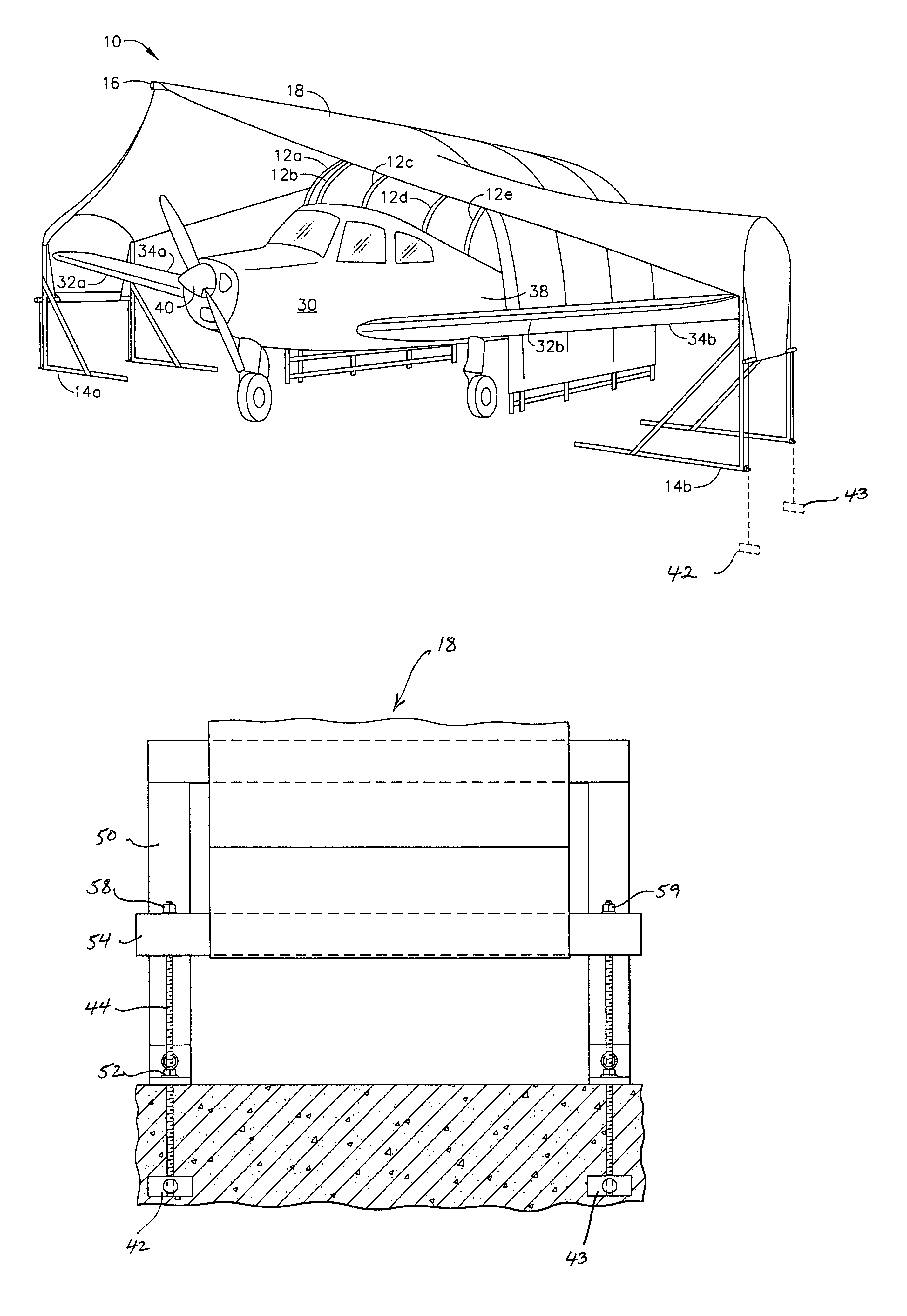
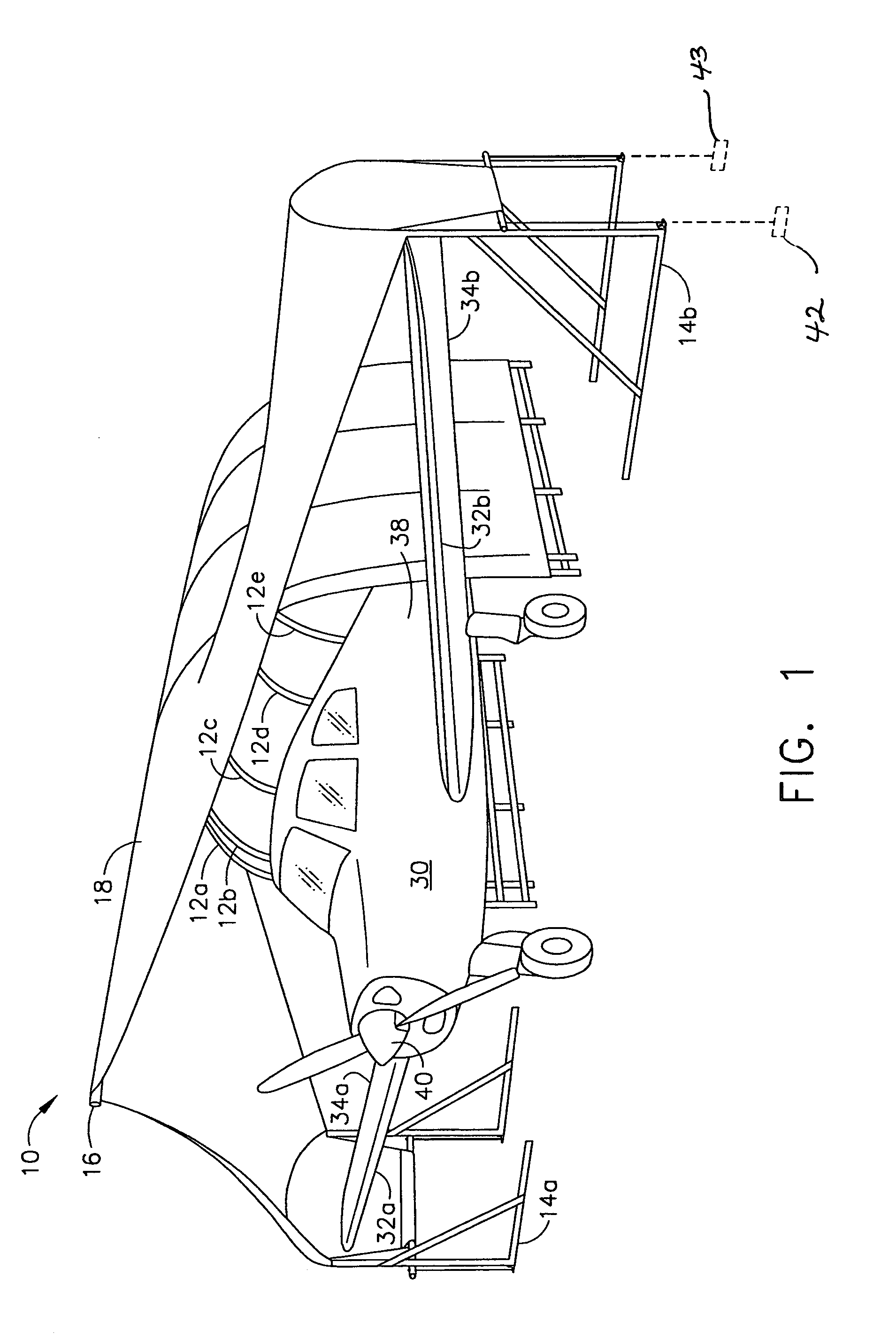
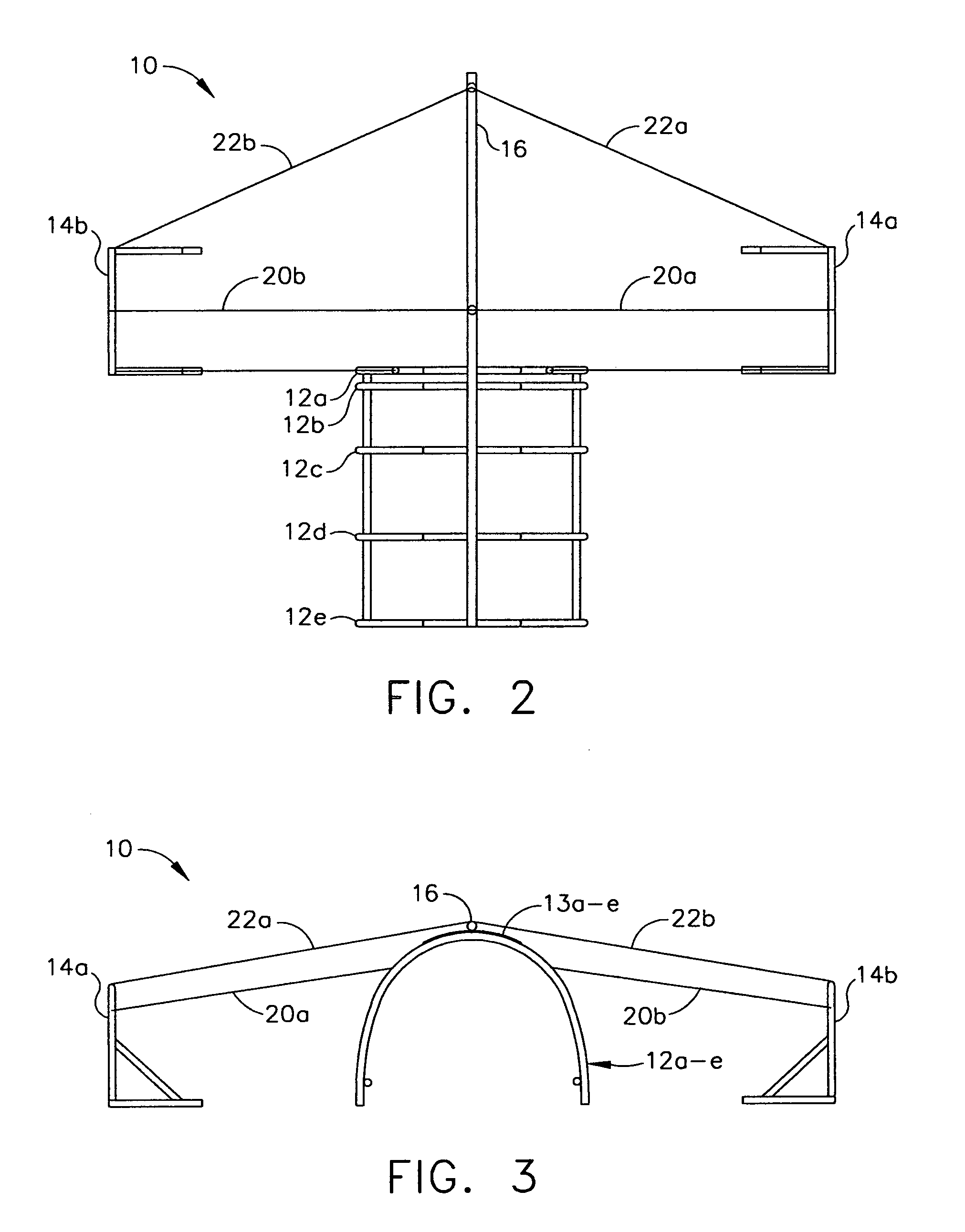
[0007]Consequently, a novel airplane shelter is described herein which enhances a structure with the best features of a cover. In order to achieve the advantages of this airplane shelter, a substantially rigid skeletal frame has been invented that, with the use of a unique cantilever structure, provides connections and support for cables and material to enclose and protect an airplane. A plurality of arched vertical support members are arranged axially along a line corresponding to the fuselage of an airplane to be sheltered. The line extends from essentially the trailing edge of the airplane's wings to a point at or just past the trailing edge of the airplane's tail assembly. A cantilever beam is attached to the apex of each arched vertical support member, forming a “spine” along the top of the aligned arched support members.
[0011]As will be seen in the following description and drawings, the claimed invention provides an airplane shelter which combines the low cost and easy assembly of a cover, while also providing the sturdy construction and ability to access the airplane found in structures. The use of a central cantilever beam and small lateral support members, instead of expensive vertical walls and horizontal ceiling structures, to support a covering material provides sufficient shelter to protect an airplane from the elements while still allowing sufficient access to the airplane for loading, unloading, maintenance, and other purposes.BRIEF DESCRIPTION OF THE DRAWINGS

Problems solved by technology

Covers, being stretched over the wings and body of the airplane, come into contact with exterior surfaces and objects, either causing damage directly or indirectly such as when dust is entrapped in the cover and wind causes the cover to flutter on the aircraft surface.
This can cause scratching and other damage to polished and / or painted surfaces, as well as causing damage to external objects such as antennae, which can lead to unsafe operating conditions.
Further, covers are often difficult for a single person to properly drape and secure over the airplane, which is very inconvenient for pilots flying solo.
Additionally, covers tend to be form fitting over the airplane, making it difficult or even impossible to perform maintenance or safety checks or to enter the aircraft.
Even further, a cover must be removed and properly stored each time the airplane is to be used, then replaced over the airplane when the airplane is returned to the flight line, adding to the time and effort required to otherwise enjoy flying.
While structures, such as traditional hangar buildings offer one-time setup, they also suffer from several disadvantages.
Structures require much more in the way of design, floor plans, materials and assembly labor than a cover, and are therefore much more expensive to produce.
Further, they often require a building foundation, depending on the type of soil, and are not easily constructed except by professionals.
Additionally, prior designs have complicated wing-spanning trusses or arches which are both expensive and difficult for the individual plane owner to assemble.
Due to the inconvenience of covers and the expense of structures, many airplane owners may opt to forego sheltering their airplanes, leaving them unprotected from the elements, leading to excessive deterioration of exterior surfaces and equipment.
Undetected, the resulting corrosion could, in time, lead to catastrophic alteration of the airfoil surfaces, causing dangerous flying conditions.
Exposure to the elements is also damaging to aircraft interiors, avionics and electronics.

Method used


Image

  • Airplane hangar
  • Airplane hangar
  • Airplane hangar

Examples


Embodiment Construction

[0022]While those skilled in the art will recognize that the present invention can easily be adapted for use with a wide variety of aircraft, the description herein assumes, but is not intended to be limited to, a single engine monoplane of size and dimensions similar to any of many makes and models presently in use.

[0023]As can be seen in FIG. 1 and in subsequent figures, the present invention provides an airplane shelter 10 for sheltering of an airplane 30. The shelter 10 is comprised of a plurality of vertical support members 12a–e, a cantilever apex beam 16, a pair of lateral support members 14a,b, a removable pole 24 and a covering material 18. Optional elements include central support cables 20a,b, forward support cables 22a,b, front door flaps 26a,b, cantilever support cable 21 and support pole 23, supplemental cantilever beams 17a, b, and walls.

[0024]The vertical support members 12a–e may be essentially arched in configuration, but may be of any of a number of shapes which w...


PUM


Abstract

A novel airplane shelter provides a plurality of arched vertical support members arranged axially along a line corresponding to the fuselage of an airplane to be sheltered. A cantilever beam is attached to the apex of each arched vertical support member, forming a “spine” along the top of the aligned arched support members. The cantilever beam is attached at one end to the rearwardmost arched support member, and the opposite end extends forwardly past the forwardmost arched support member to a point corresponding to the forwardmost point of an airplane to be sheltered. Separate lateral support members are placed at points corresponding to the wingtips of the airplane. The result is an open frame that defines a volume capable of enclosing an airplane. A covering material is placed over the open frame and stretched taut or otherwise secured over the entire structure.

Description

[0001]This Application is a Continuation-in-part of Ser. No. 09 / 891,426, filed Jun. 27, 2001, now U.S. Pat. No. 6,758,230.BACKGROUND AND SUMMARY OF THE INVENTION[0002]A need has long existed for a reliable, convenient and relatively inexpensive hangar or shelter to protect airplanes and other winged aircraft, such as gliders, from the elements while parked on a flight line or otherwise out of use on the ground.[0003]Currently, the two major existing solutions for sheltering airplanes are covers and structures. Covers, such as simple canvas or plastic tarpaulins, are relatively inexpensive, but suffer from several disadvantages. Covers, being stretched over the wings and body of the airplane, come into contact with exterior surfaces and objects, either causing damage directly or indirectly such as when dust is entrapped in the cover and wind causes the cover to flutter on the aircraft surface. This can cause scratching and other damage to polished and / or painted surfaces, as well as ...

Claims


Application Information

Patent Timeline
IPC IPC(8): E04H15/00E04B1/34E04B1/342E04H6/44
CPCE04H6/44Y10S135/907
Inventor BOGART, DONALD W.
Owner BOGART DONALD W
Learn More