Dental tray assembly

Inactive Publication Date: 2006-08-15
DR DICK BARNES GROUP
View PDF20 Cites 18 Cited by
  • Summary
  • Abstract
  • Description
  • Claims
  • Application Information

AI Technical Summary

Benefits of technology

[0011]It has been recognized that it would be advantageous to develop a dental tray assembly that can be used to temporarily store oral prosthetics while maintaining identification of each prosthetic. In addition, it has been reco

Problems solved by technology

This makes identification of oral prosthetics difficult without carefully maintaining each prosthetic in its particular package.
In addition to the problems inherent in tracking the identity of oral prosthetics, problems also arise during application of oral prosthetics due to the adhesive that is generally applied to the prosthetic prior to attaching or bonding the prosthetic to the tooth structure.
As the adhesive material on the prosthetic must be kept clean from contaminates, placing the wet prosthetic aside can be problematic in that the adhesive may become contaminated while the prosthetic is set aside.
Also, excess adhesive may fall or drip from the prosthetic and contaminate otherwise clean surfaces in the dental office.
If the “wet” prosthetic is allowed to sit for too long in an environment in which it is exposed to natural or artificial light, the adhesive may begin curing prematurely due to the UV content of the natural or artificial light.
This can result in a poor bond being formed between

Method used


Image

  • Dental tray assembly
  • Dental tray assembly
  • Dental tray assembly

Examples


Embodiment Construction

[0032]Reference will now be made to the exemplary embodiments illustrated in the drawings, and specific language will be used herein to describe the same. It will nevertheless be understood that no limitation of the scope of the invention is thereby intended. Alterations and further modifications of the inventive features illustrated herein, and additional applications of the principles of the inventions as illustrated herein, which would occur to one skilled in the relevant art and having possession of this disclosure, are to be considered within the scope of the invention.

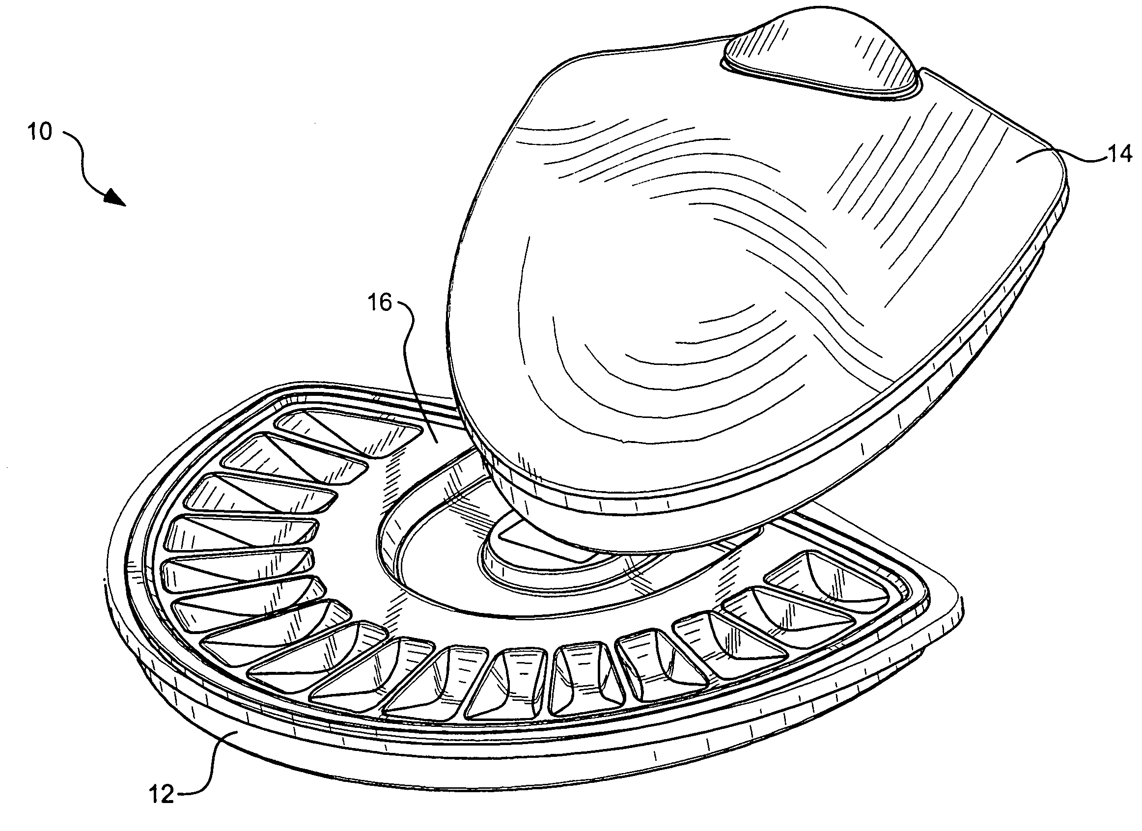
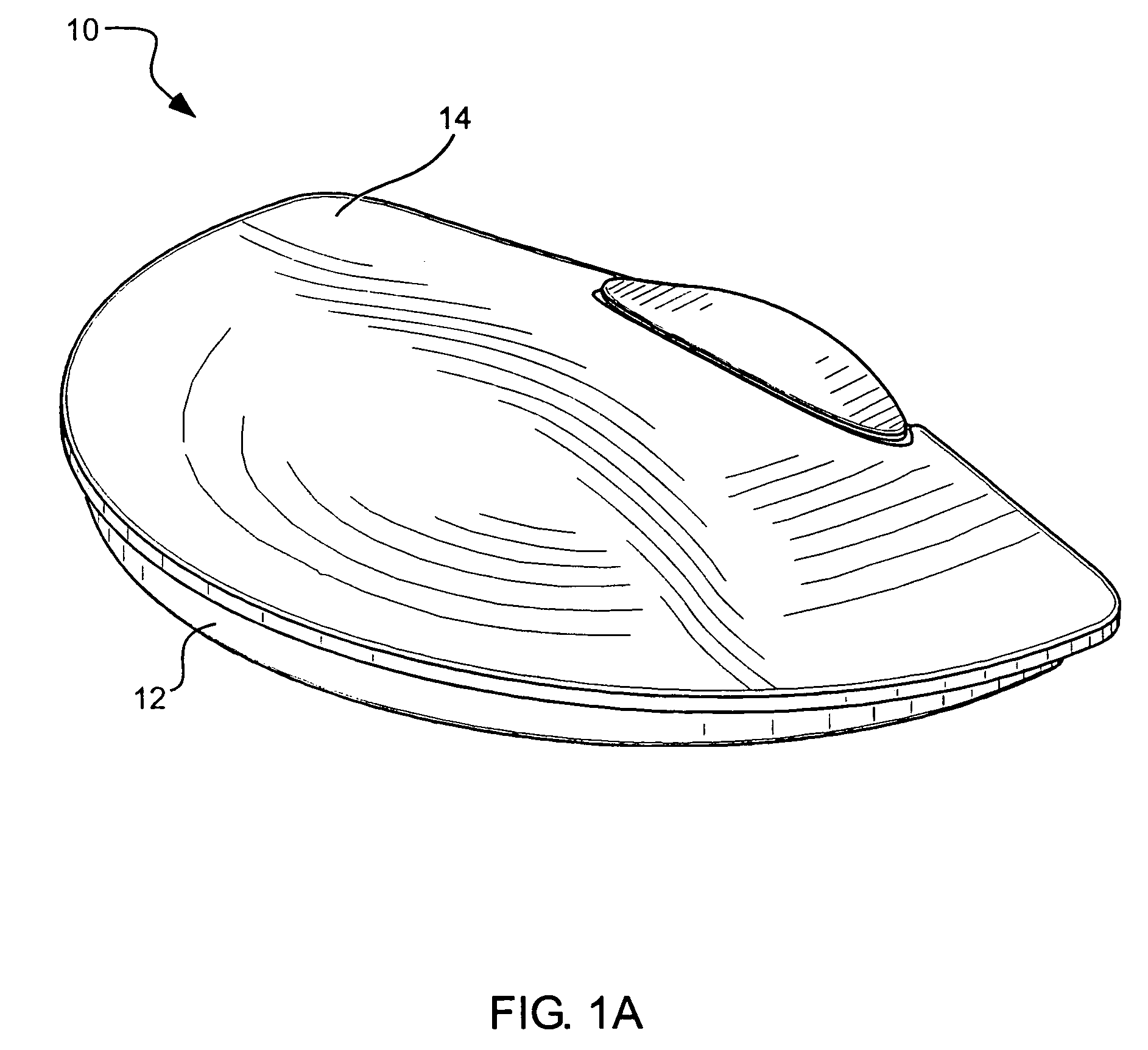
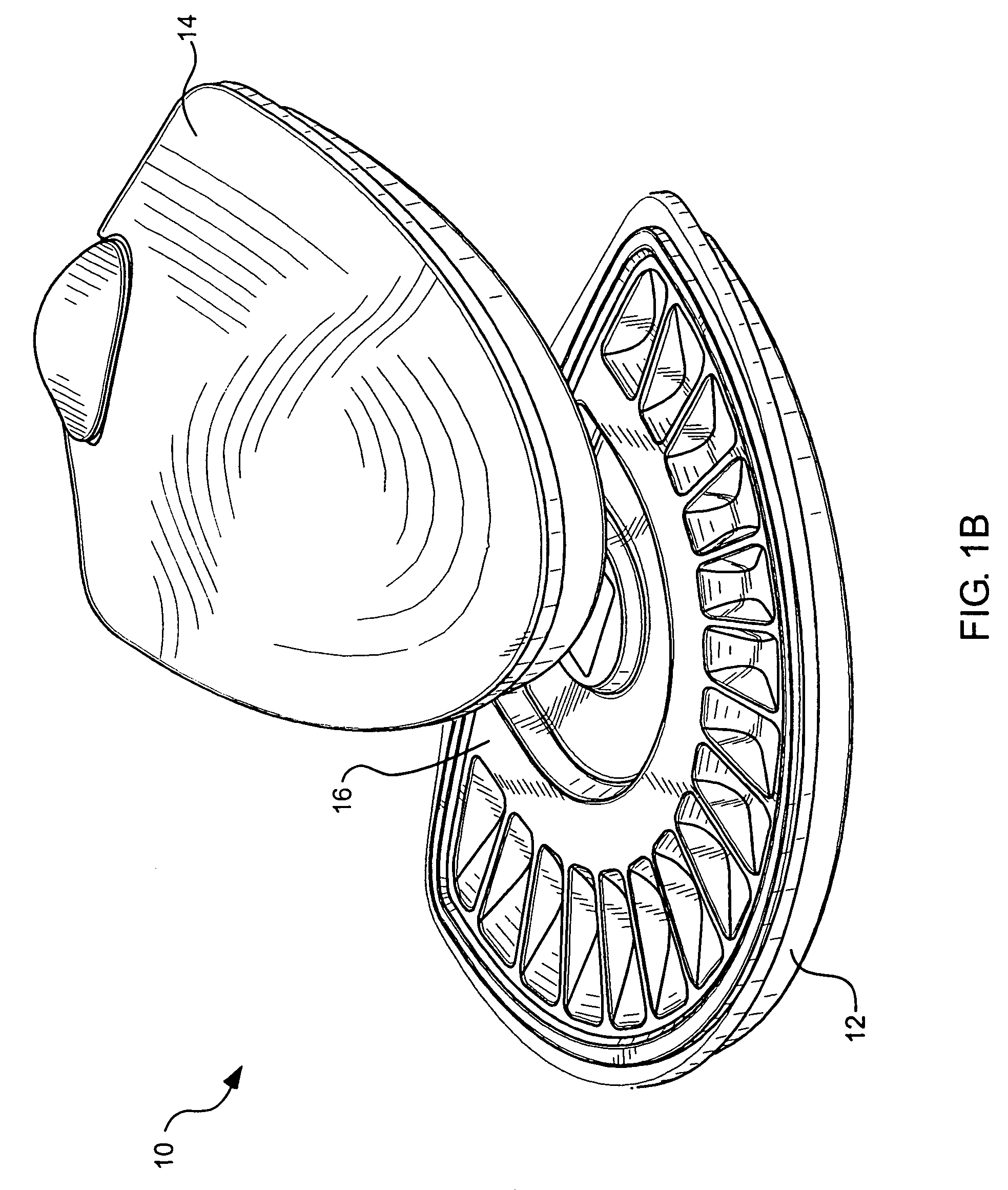
[0033]As illustrated in FIGS. 1A and 1B, a dental tray assembly, indicated generally at 10, is provided in accordance with one aspect of the present invention. The assembly is shown in FIG. 1A in a first, closed position and the assembly is shown in FIG. 1B in a second, open position. The assembly generally includes a base 12 and a cover 14. As described in more detail below, the cover and the base can be hingedl...


PUM


Abstract

A dental tray assembly for storage of oral prosthetics includes a base and a cover, associated with the base and being configured to be alternately positioned relative to the base in a first, closed position, and a second, open position. A biasing element interconnects the base and the cover to provide a biasing force between the cover and the base, the biasing force varying with position of the cover relative to the base to provide an attractive force between the cover and the base when the cover is in the first, closed position, and a repellant force between the cover and the base when the cover is in the second, open position. A storage tray is nestable within the base, the storage tray including at least two compartments, each compartment being configured to receive and store an oral prosthetic therein.

Description

[0001]Priority is claimed of U.S. Provisional Application No. 60 / 468,831, filed May 7, 2003, which is hereby incorporated herein by reference.BACKGROUND OF THE INVENTION[0002]1. Field of the Invention[0003]The present invention relates generally to a dental tray assembly. More particularly, the present invention relates to a dental tray assembly for the temporary storage of oral prosthetics by dental practitioners.[0004]2. Related Art[0005]Dental practitioners often apply oral prosthetics to dental patients to enhance the appearance of, repair damage to, or replace natural tooth structure. Dental prosthetics can be categorized into two primary types: permanent prosthetics, which are designed to remain on the tooth structure; and removable prosthetics, which can be removed and subsequently replaced by the patient. Removable prosthetics include devices such as dentures, retainers, etc. Examples of permanent oral prosthetics include dental crowns, caps, bridges, orthodontics, etc. In t...

Claims


Application Information

Patent Timeline
IPC IPC(8): A61B19/02B65D83/10A61C19/10
CPCA61C19/10
Inventor BARNES, RICHARD
Owner DR DICK BARNES GROUP
Why Eureka
Try Eureka