Deposition of integrated circuit fabrication materials using a print head

a technology of integrated circuits and print heads, applied in the direction of individual semiconductor device testing, semiconductor/solid-state device testing/measurement, instruments, etc., can solve the problems of not being able to use a tuned timing pattern, requiring relatively expensive electronics and bulky cabling, and using a relatively low-cost print head

Active Publication Date: 2006-08-15
NOVELLUS SYSTEMS
View PDF5 Cites 19 Cited by
  • Summary
  • Abstract
  • Description
  • Claims
  • Application Information

AI Technical Summary

Problems solved by technology

This approach, however, requires relatively expensive electronics and bulky cabling as each nozzle may have to be connected to its own drive circuit with independent timing.
Using a relatively low-cost, off-the-shelf print head poses its share of problems because such a

Method used


Image

  • Deposition of integrated circuit fabrication materials using a print head
  • Deposition of integrated circuit fabrication materials using a print head
  • Deposition of integrated circuit fabrication materials using a print head

Examples


Embodiment Construction

[0022]In the present disclosure, numerous specific details are provided such as examples of systems, components, and methods to provide a thorough understanding of embodiments of the invention. Persons of ordinary skill in the art will recognize, however, that the invention can be practiced without one or more of the specific details. In other instances, well-known details are not shown or described to avoid obscuring aspects of the invention.

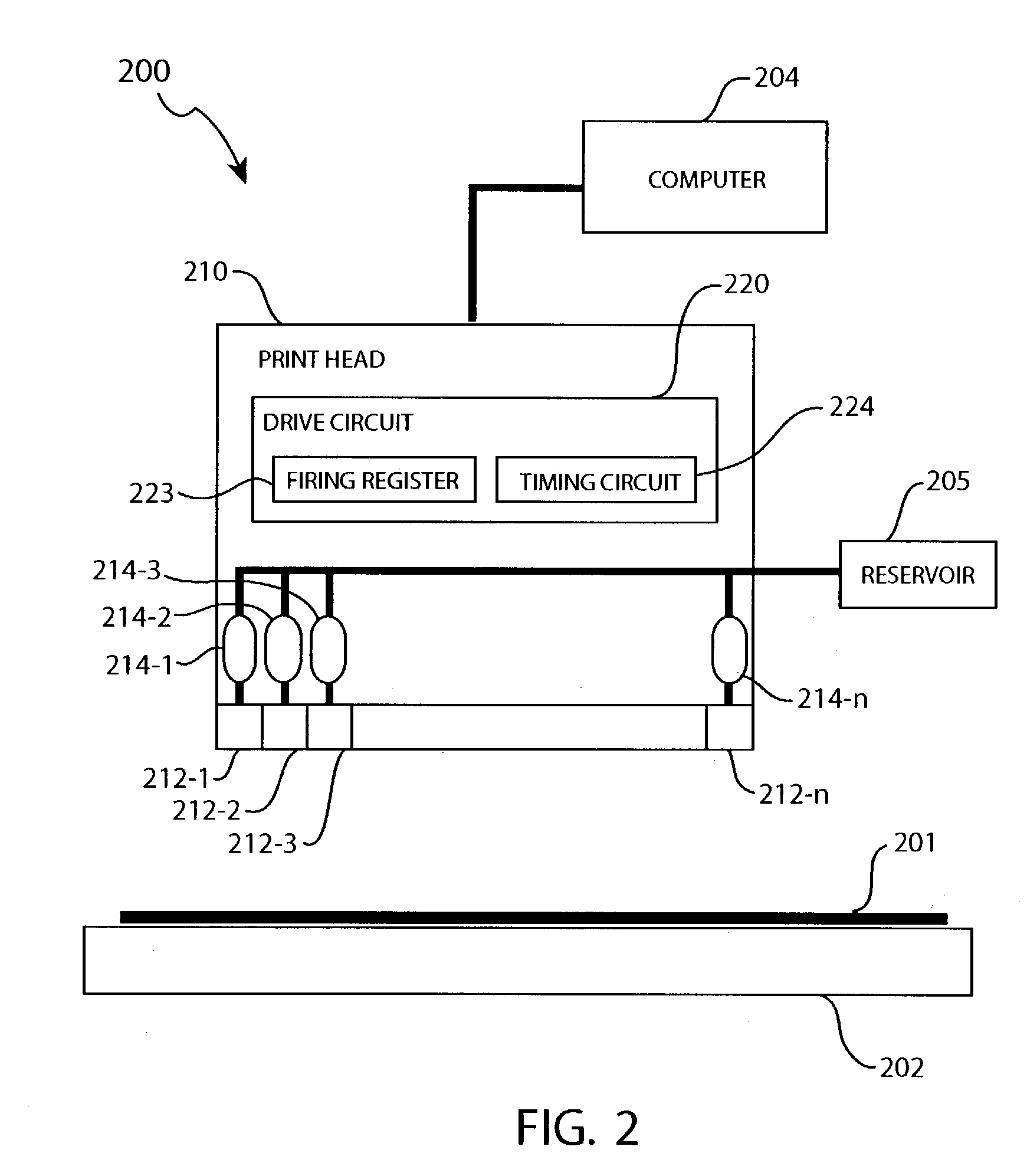
[0023]FIG. 2 schematically shows a an integrated circuit (IC) fabrication system 200 in accordance with an embodiment of the present invention. System 200 includes a computer 204, a print head 210, a pedestal 202, and a reservoir 205. Pedestal 202 supports a substrate 201, which may be a semiconductor wafer, for example. System 200 may be employed to deposit an IC fabrication material on substrate 201. Examples of IC fabrication materials that may be deposited on a substrate using system 200 include dielectric materials, photoresists, developer...


PUM


Abstract

In one embodiment, an integrated circuit (IC) fabrication material is dispensed from a print head by dividing its nozzles into several groups, and sequentially allowing each group to fire. The nozzles may be grouped based on the amounts of material they dispense. For example, the nozzles may be grouped by drop volume or drop mass. In one embodiment, an IC fabrication material is dispensed on a substrate by controlling a firing sequence of a nozzle to promote merging of material on the substrate. The firing sequence may also be altered to take into account the firing sequence of adjacent nozzles.

Description

BACKGROUND OF THE INVENTION[0001]1. Field of the Invention[0002]The present invention relates generally to integrated circuit (IC) fabrication, and more particularly but not exclusively to deposition of IC fabrication materials using a print head.[0003]2. Description of the Background Art[0004]The use of ink jet technology to print on paper is well known. A typical ink jet print head has several nozzles that are coupled to an ink reservoir. Ink from the reservoir are dispensed through the nozzles to form a pattern on paper. The ink jet print head may be scanned relative to the paper, or vice versa, to cover a large area.[0005]FIG. 1 schematically illustrates the operation of an exemplary ink jet print head 20. Print head 20 may be of the type available from Ink Jet Technology Inc. of San Jose, Calif., for example. Print head 20 may have any number of nozzles 22 (i.e., 22-1, 22-2, . . . ) but only four are shown for clarity of illustration. A digital firing pattern may be serially lo...

Claims


Application Information

Patent Timeline
IPC IPC(8): H01L21/31
CPCB41J2/04506B41J2/04543B41J2/04573B41J2/04581B41J2/0456H01L51/0005H10K71/135
Inventor MEINHOLD, HENNER W.CAI, WAYNEREA, MARK L.CHINCHWADKAR, SACHIN M.
Owner NOVELLUS SYSTEMS
Why Eureka
Try Eureka