
Surround sound loudspeaker system

a loudspeaker and surround sound technology, applied in the field of surround sound loudspeakers, can solve the problems of customer resistance, additional cost of two full-range rear loudspeakers, and failure of quadraphonic sound systems,

Inactive Publication Date: 2006-08-15
KRAUSSE HOWARD
View PDF5 Cites 51 Cited by
  • Summary
  • Abstract
  • Description
  • Claims
  • Application Information

AI Technical Summary

Benefits of technology

"The invention is about creating a realistic \"virtual surround sound\" in a home theater setting using a small number of loudspeakers. The loudspeakers are placed in a way that their sound energy is directed towards the listener, while also creating a \"virtual\" audience behind the listener. The invention uses a special sound field called a skewed hypercardioid, which is designed to minimize the impact of early sound arrivals and feedback squeal. The invention can be applied to both computer monitors and large auditoriums, and it provides a flexible solution for creating specific sound energy patterns in enclosed listening spaces. The invention also allows for the creation of a reflected \"phantom loudspeaker\" with accurate tonal balance in all directions from the loudspeakers."

Problems solved by technology

Four channel or quadraphonic sound systems comprising full-range right and left front stereo loudspeakers and full-range right and left rear loudspeakers were developed, however, the quadraphonic sound system was a marketing failure, particularly in the private home market.
One of the reasons for the marketing failure is reputed to be the difficulty in placing four large separate loudspeakers in the proper locations about the listener for best acoustic reproduction which typically conflicts with other decorating and furniture placement considerations.
Another reason often cited is the additional cost of the two full-range rear loudspeakers.
Long wires must be installed for the two rear loudspeakers and this factor has caused some customer resistance.
The Dolby® AC3™ system is now being marketed with five full-range loudspeakers or five small loudspeakers plus a subwoofer, however, customer acceptance has not yet been proven.

Method used


Image

  • Surround sound loudspeaker system
  • Surround sound loudspeaker system
  • Surround sound loudspeaker system

Examples


Embodiment Construction

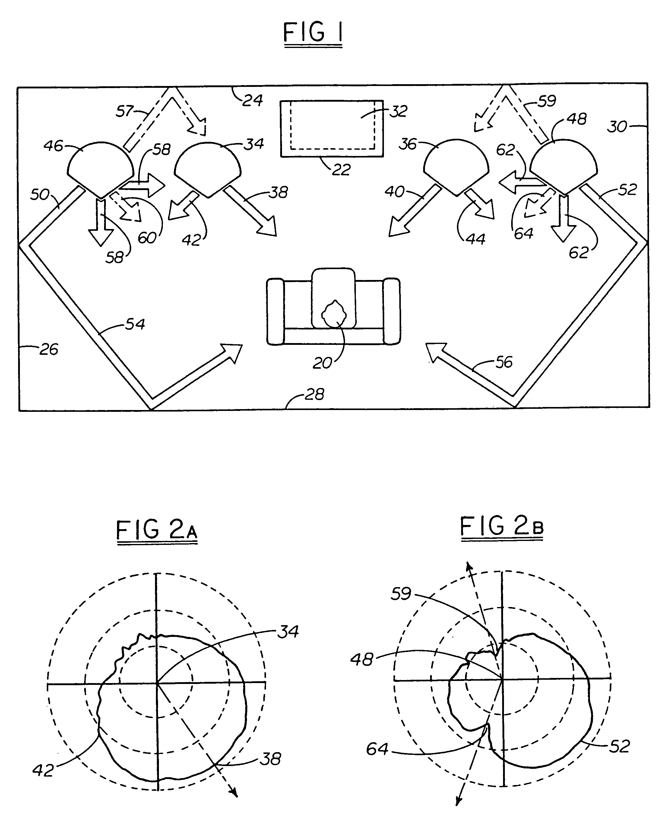
[0074]In FIG. 1 a home theater setting comprises a user 20 seated at some distance from a television screen 22 within a room having a front wall 24, left side wall 26, back wall 28 and right side wall 30. The television screen 22 may be a self-contained television set or movie screen with a ceiling mounted projector, for example.

[0075]A center channel loudspeaker 32 may be located above, below or behind the television screen 22. There also is typically a “subwoofer” which has considerable freedom of placement, especially if the other speakers are small. To either side of the screen 22 are left front (LF) 34 and right front (RF) 36 loudspeakers so placed and constructed as to direct maximum sound energy toward the user 20 as indicated by the larger arrows 38 (LF) and 40 (RF). Some sound energy (arrows 42 (LF) and 44 (RF)) is directed away from the listener by the “direct sound” loudspeakers, however, this sound energy provides desirable ambiance and correct left and right channel bal...


PUM


Abstract

A single loudspeaker has a substantially single-point source of sound energy derived from multiple drivers to provide a surround sound effect. The surround sound is effective for listeners close to the single loudspeaker or substantially distant within a room. The physical size of the loudspeaker is convenient for placement on top of a computer monitor or television set. The single loudspeaker produces a dynamically variable energy gradient between the listener's right and left ears and the perception of sound emanating from changing locations in the space surrounding the loudspeaker. The placement of a plurality of these loudspeakers surrounding the expected listener location allows the coverage of larger spaces with separate dynamically variable energy gradient pairs.

Description

[0001]This application is a continuation-in-part of application Ser. No. 08 / 542,451, filed Oct. 12, 1995, now U.S. Pat. No. 5,809,150, in turn based on provisional patent application Ser. No. 60 / 000,534 filed Jun. 28, 1995.BACKGROUND OF THE INVENTION[0002]The field of the invention pertains to audio loudspeakers used in plural to realistically recreate the direct and ambient sound of an audio only, or an audio visual work such as a movie or television program and, in particular, in a home theater setting to provide sound from all directions to the viewer-listener. This invention also pertains to audio loudspeakers used for reproducing in a more realistic manner audio recordings in general (“auralization”).[0003]Stereophonic sound systems utilizing two loudspeakers, both being forward of the listener, are common. More recently bass units (subwoofers) have been added as a third separate loudspeaker. The main purpose of adding this third speaker is to allow smaller left and right speak...

Claims


Application Information

Patent Timeline
Patent Type & Authority Patents(United States)
IPC IPC(8): H04R5/02
CPCH04R5/02H04R2205/024H04R2205/022H04R1/347H04R3/14
Inventor EBERBACH, STEVEN J.
Owner KRAUSSE HOWARD
Learn More