

Driving force transmission mechanism, image forming apparatus equipped with such a mechanism, and process unit of such an apparatus
a transmission mechanism and driving force technology, applied in the direction of electrographic process apparatus, instruments, optics, etc., can solve the problems of degrading image quality, degrading image quality, and disturbing contact between the two systems
- Summary
- Abstract
- Description
- Claims
- Application Information
AI Technical Summary
Benefits of technology
Problems solved by technology
Method used
Image

Examples
embodiment 1
[0036]Referring to FIGS. 1 and 2, the first embodiment of the present invention will be described.
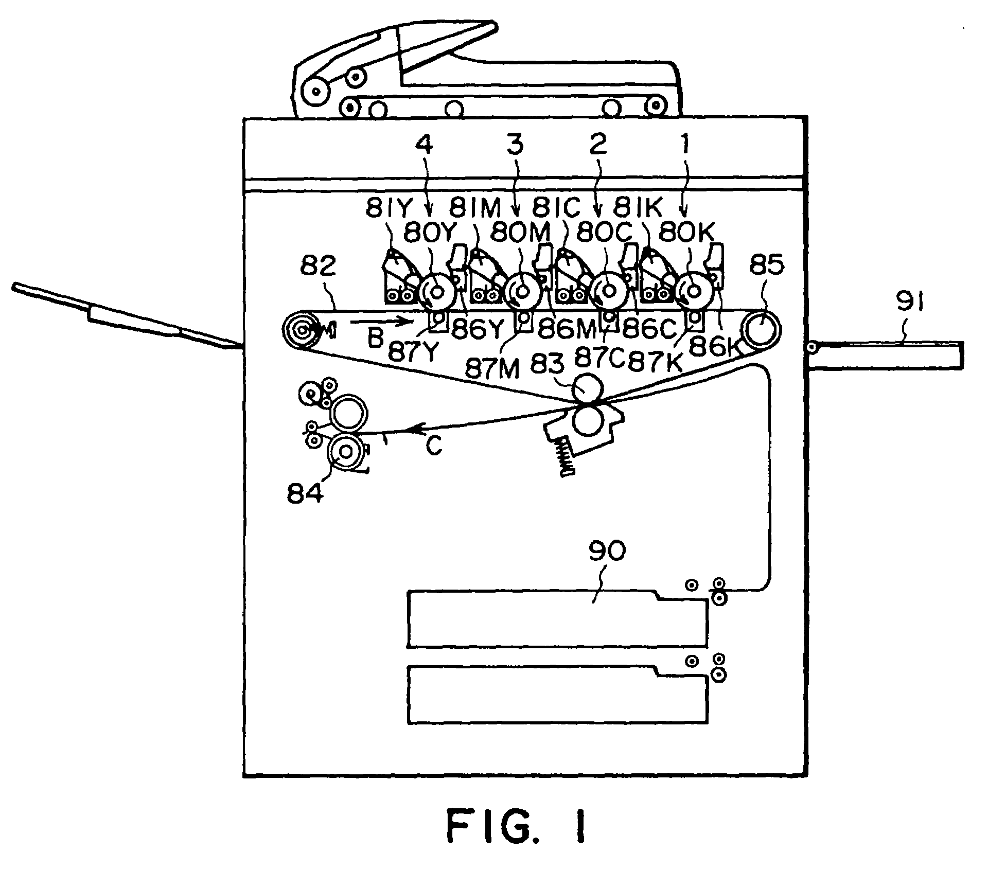
[0037]First, the image forming apparatus in this embodiment will be described with reference to FIG. 1. The image forming apparatus in this embodiment is an electrophotographic color image forming apparatus, which employs an intermediary transfer belt 82. It also has yellow, magenta, cyan, and black image forming stations 1, 2, 3 and 4, which are disposed in parallel along the horizontal portion of the intermediary transfer belt 82. In the drawing, referential codes Y, M, C and K mean yellow, magenta, cyan, and black colors, correspondingly. Although the image forming station arrangement order is Y, M, C and K from the left in this embodiment, it may be different from the order in this embodiment.
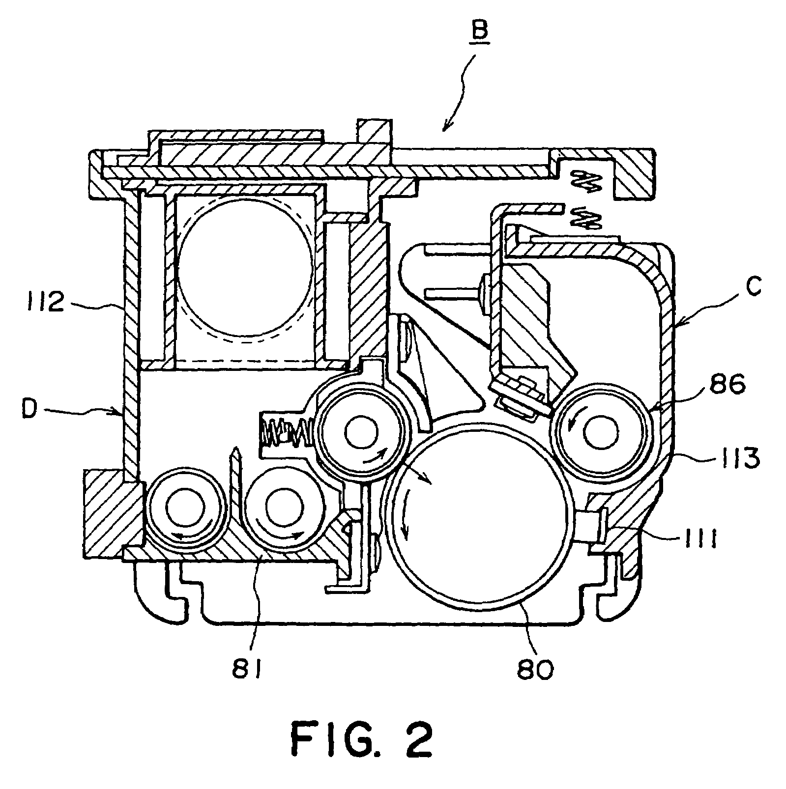
[0038]The image forming stations 1–4 comprises: photoconductive drums 80Y, 80M, 80C and 80K, as image bearing members; charging apparatuses 86Y, 86M, 86C and 86K; an unshown exposing apparatus;...
embodiment 2
[0056]Next, the second embodiment of the present invention will be described with reference to FIG. 4.
[0057]In the first embodiment, the extension portion 130 of the gear shaft 13 is used as the shaft for the shaft-hole engagement. However, in this embodiment, the shaft used for the shaft-hole engagement is rendered independent from the gear shaft 13.
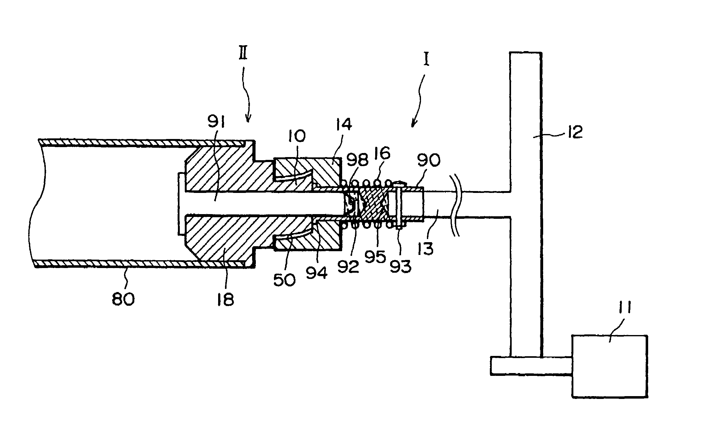
[0058]Referring to FIG. 4, a driving system I comprises a motor 11, a driving gear 12, a gear shaft 13, and a second coupling portion 14. The second coupling portion 14 and gear shaft 13 are connected by a connecting member 90, and the second coupling portion 14 is attached to the drum side end portion of the connecting member 90, and connecting member 90 functions as the center shaft for the second coupling portion 14. One end of the connecting member 90 is provided with a hole 92, and a collar 94, which are located at the drum side end to accurately position the second coupling member 14, whereas the other end of the connecting member...
embodiment 3
[0067]Next, referring to FIG. 5, the third embodiment of the present invention will be described. A drum flange 18 is provided with a cylindrical elastic member 5 as a braking member, which is formed of rubber or the like. Referring to FIG. 6, the details of the elastic member 5 will be described. The elastic member 5 is provided with a center hole 6, which is a through hole, into which the extension portion 130 of a gear shaft 13 is engaged. The gear shaft 13 also constitutes the central shaft of the coupling. The internal diameter of the hole 6 is smaller than that of the through hole 19 of the drum flange 18, which extends in the axial direction of the drum flange 18 inclusive of the first coupling portion 10, that is, a projection in the form of a polygonal pillar; the internal diameter of the hole 6 is such that when the extension portion 130 of the gear shaft 13 is in the through hole 19, there is no play between the drum flange 18 and the extension portion 130 of the gear sha...
PUM
 Abstract
Description
Claims
Application Information