

Debugging Method
a debugging method and debugging technology, applied in the field of debugging, can solve the problems of insufficient high-level language command units, the debugging itself, and the inability to accurately debug
- Summary
- Abstract
- Description
- Claims
- Application Information
AI Technical Summary
Problems solved by technology
Method used
Image

Examples
first embodiment
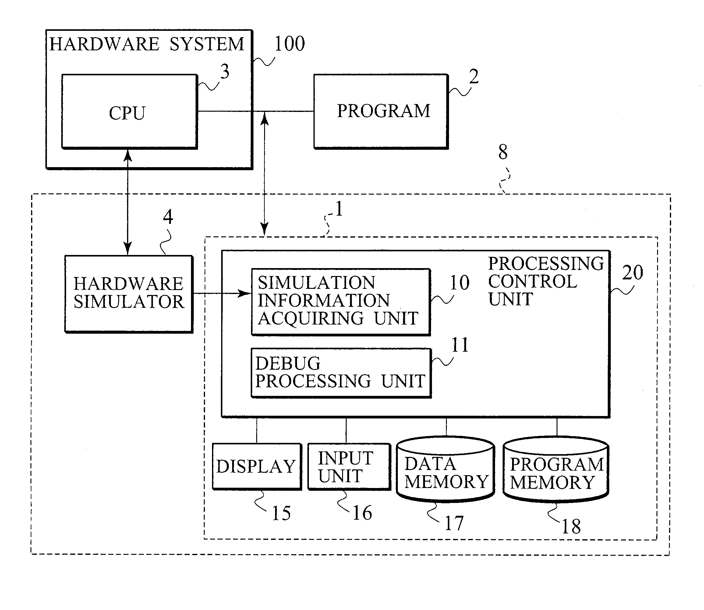
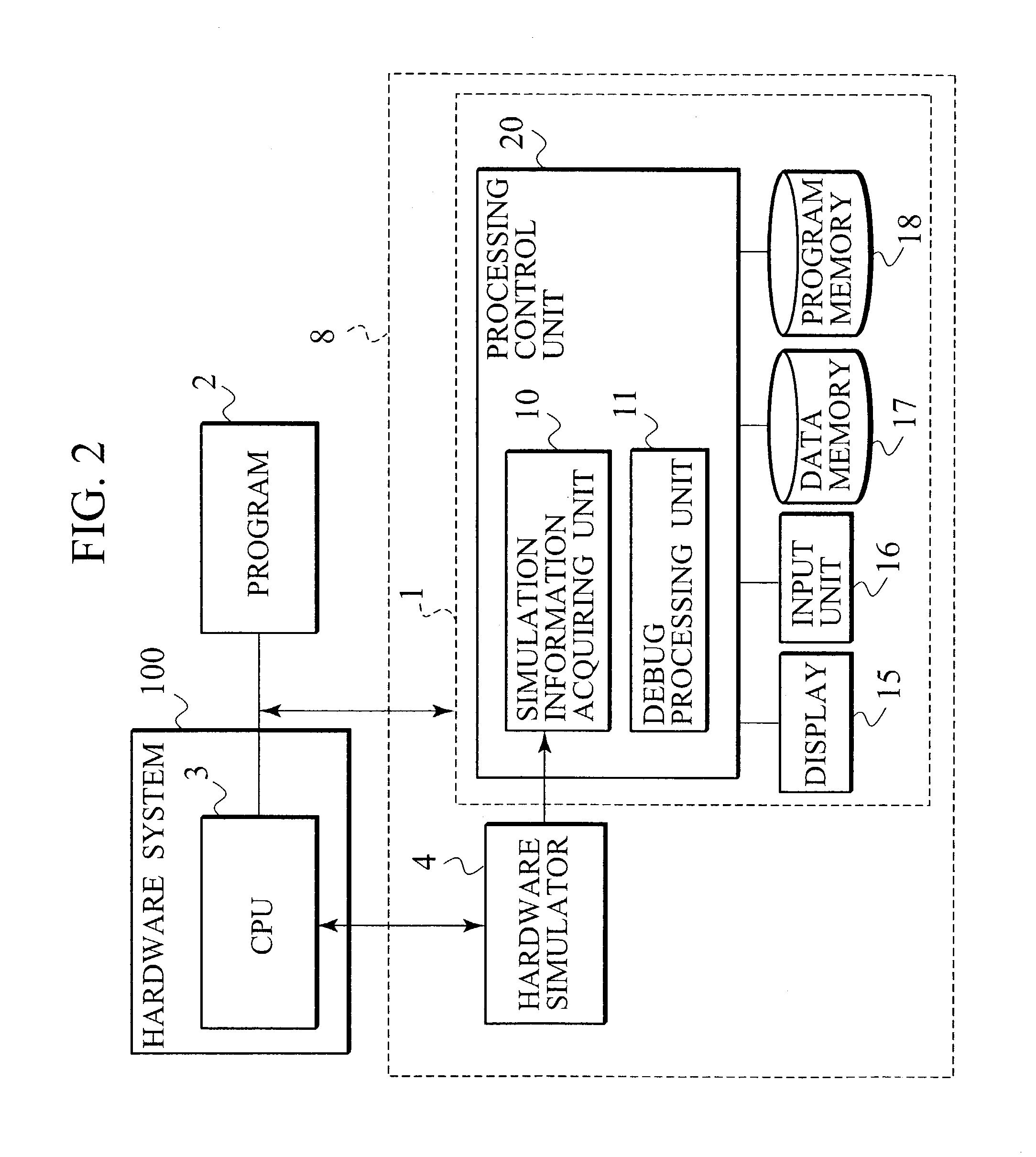
[0037]FIG. 2 is a view showing an execution environment of a software debugger according to a first embodiment of the present invention. As shown in FIG. 2, a system-level debugger 8 of the first embodiment includes a software debugger 1, and a hardware simulator 4 connected to a hardware system 100. A program 2 to be debugged is executed by a central processing unit (CPU) 3 of the hardware system 100. An operation of the entire system (target system) 100 including the CPU 3 is simulated by the hardware simulator 4. The software debugger 1 is connected to the hardware simulator 4 to debug the program 2 executed on the CPU 3. The program 2 is software such as an application, an OS or a device driver. The software debugger 1 includes a processing control unit 20, a display 15 connected to the processing control unit 20, an input unit 16, a data memory 17, and a program memory 18. The processing control unit 20 is provided with a simulation information acquiring unit 10 and a debug pro...
example 1-1
METHOD EXAMPLE 1-1
[0057]The software debugging method of the first embodiment of the present invention enables all the cycles to be checked by setting a step width of debugging in the debug processing unit 11 of FIG. 2 to one cycle.
[0058]As shown in FIG. 6, program counters cannot be traced at all the cycles with the step width in the high-level language by the software debugger 12. Thus, in the debugging method of the first embodiment, all the cycles are checked by setting the step width to one cycle.
[0059]FIG. 8 is a view showing a step width at a cycle level when debugging is carried out by the debugging method of the first embodiment in execution of the program of FIG. 4 on the CPU 3 of the target system 100 of FIG. 3. It can be understood that stalling for four cycles occurs with a first execution command b=10, stalling for one cycle occurs with a third execution command a=b+c, stalling for one cycle occurs with a fourth execution command a=b+c, and stalling for four cycles occ...
example 1-2
METHOD EXAMPLE 1-2
[0061]In a second specific example of a debugging method related to the first specific example of the first embodiment, the debug processing unit 11 of FIG. 2 pays attention to pipeline stage information of the CPU 3 contained in information acquired from the hardware simulator 4, and sets a step width for each change in the execution command executed at each pipeline stage.
[0062]A sequence of execution commands executed on the CPU 3 is normally similar at any of the pipeline stages under observation to unless a factor that disrupts the execution sequence is present. However, a timing (cycle) for execution varies from pipeline stage to pipeline stage. Also, a change made in the execution sequence of the commands by a jumping command, a branching command or an exception causes a problem in that the sequence of execution commands to be executed is different depending on the pipeline stage under consideration. For example, as shown in FIG. 22, if the occurrence of an ...
PUM
 Abstract
Description
Claims
Application Information