Wave antenna wireless communication device and method

a wireless communication device and antenna technology, applied in the field of wave antennas, can solve the problems of tire tearing, wireless communication device and antenna, stretching and compression, tire damage,

Inactive Publication Date: 2006-08-22
MINERAL LASSEN LLC
View PDF76 Cites 28 Cited by
  • Summary
  • Abstract
  • Description
  • Claims
  • Application Information

AI Technical Summary

Benefits of technology

[0009]The wave antenna is capable of stretching when subjected to a force without being damaged. The wave antenna can also provide improved impedance matching capability between the antenna and a wireless communication device because of the reactive interaction between different sections of the antenna conductor. In general, varying the characteristics of the conductor wire of the wave antenna, such as diameter, the angle of the curves, the lengths of the sections formed by the curves, the period, phase, and / or amplitude of the sinusoid, and the type of conductor wire, will modify the cross coupling and, hence, the impedance of the wave antenna.
[0017]In another embodiment, the wireless communication device is coupled to a wave antenna and is placed inside a tire so that information can be wirelessly communicated from the tire to an interrogation reader. The wave antenna is capable of stretching and compressing, without being damaged, as the tire is stretched and compressed during its manufacture and pressurization during use on a vehicle.

Problems solved by technology

For example, too little pressure in a tire during its use can cause a tire to be damaged by the weight of a vehicle supported by the tire.
Too much pressure can cause a tire to rupture.
This results in stretching and compression of the wireless communication device and antenna whenever the tire is stretched and compressed.
Often, the antenna is stretched and subsequently damaged or broken, thereby either disconnecting the wireless communication device from an antenna or changing the length of the antenna, which changes the operating frequency of the antenna.
In either case, the wireless communication device may be unable to communicate properly when the antenna is damaged or broken.

Method used


Image

  • Wave antenna wireless communication device and method
  • Wave antenna wireless communication device and method
  • Wave antenna wireless communication device and method

Examples


Embodiment Construction

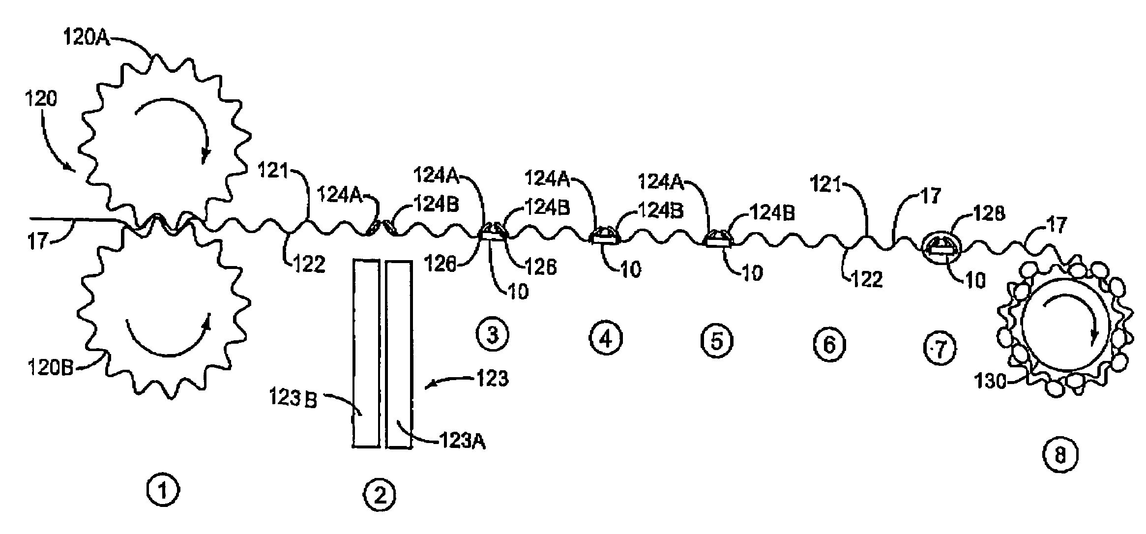
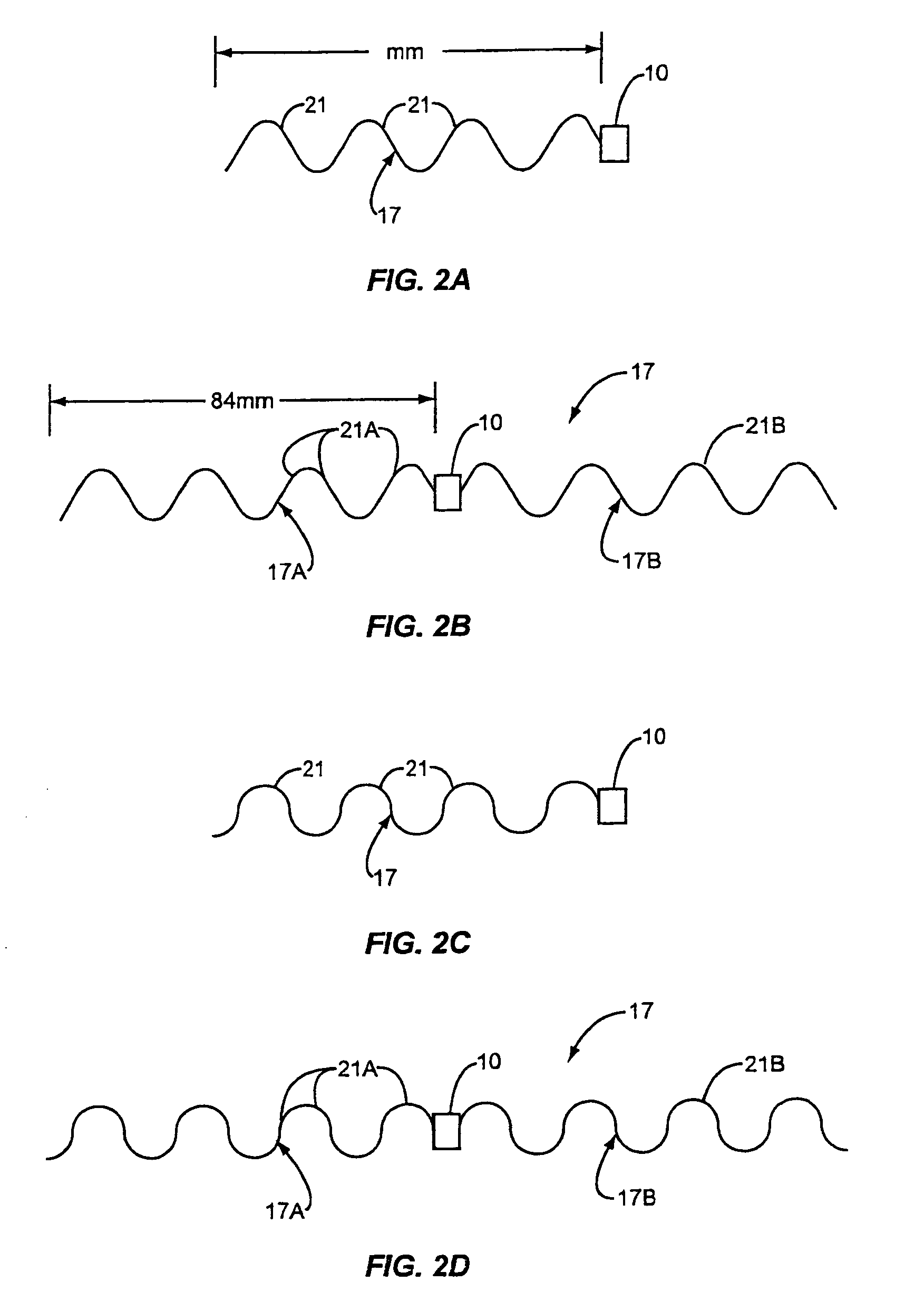
[0052]The present invention relates to a wave antenna that is coupled to a wireless communication device, such as a transponder, to wirelessly communicate information. The wave antenna may be a conductor shaped in the form of a sinusoid to form a sinusoidal-shaped wave antenna, or a semi-circle to form a semi-circle-shaped wave antenna. The wave antenna is formed by a curve placed in a substantially straight conductor to form at least two different sections wherein at least one section of the conductor is curved at an angle of less than 180 degrees with respect to the other.

[0053]This application is a continuation of U.S. Pat. No. 6,853,347, which is a continuation of U.S. Pat. No. 6,903,704, which is a continuation-in-part of U.S. Pat. No. 6,630,910 entitled “Wave Antenna Wireless Communication Device and Method,” all of which are incorporated herein by reference in their entirety.

[0054]A wave antenna has curves that allow stretching or compressing of the conductor comprising the a...


PUM


Abstract

A wireless communication device coupled to a wave antenna that provides greater increased durability and impedance matching. The wave antenna is a conductor that is curved in alternating sections. The wireless communication device is coupled to the wave antenna to provide wireless communication. The wireless communication device and wave antenna may be placed on objects, goods, or other articles of manufacture that are subject to forces such that the wave antenna may be stretched or compressed during the manufacture and / or use of such object, good or article of manufacture. The wave antenna, because of its curved structure, is capable of stretching and compressing more easily than other structures, reducing the wireless communication device's susceptibility to damage or breakage that might render the wireless communication device coupled to the wave antenna unable to properly communicate information wirelessly.

Description

RELATED APPLICATION[0001]This application is a continuation of U.S. patent application Ser. No. 10 / 637,098, filed Aug. 8, 2003, now U.S. Pat. No. 6,853,347, which is a continuation of U.S. patent application Ser. No. 10 / 228,180, filed Aug. 26, 2002, now U.S. Pat. No. 6,903,704, which is a continuation-in-part of U.S. patent application Ser. No. 10 / 012,206, entitled “Wave Antenna Wireless Communication Device and Method,” filed on Oct. 29, 2001, now U.S. Pat. No. 6,630,910, priority from the filing dates of which is hereby claimed under 35 U.S.C. §120.FIELD OF THE INVENTION[0002]The present invention relates to a wave antenna coupled to a wireless communication device so that the wireless communication device can wirelessly communicate information.BACKGROUND OF THE INVENTION[0003]Wireless communication devices are commonly used today to wirelessly communicate information about goods. For example, transponders may be attached to goods during their manufacture, transport and / or distrib...

Claims


Application Information

Patent Timeline
Patent Type & Authority Patents(United States)
IPC IPC(8): H01P11/00B60C23/04G06K19/077H01Q1/22H01Q1/36H01Q1/38H01Q9/16H01Q9/28
CPCB60C23/04B60C23/0433B60C23/0452G06K19/07728G06K19/07749G06K19/07758G06K19/07764G06K19/07786H01Q1/22H01Q1/2241H01Q1/36H01Q1/38H01Q9/16H01Q9/26H01Q9/28H01Q9/285B60C23/0408Y10T29/49016
Inventor FORSTER, IAN JAMESHORRELL, PETER ROBERT GEORGEKING, PATRICK F.PFEIFFER, MICHAEL J.
Owner MINERAL LASSEN LLC
Why Eureka
Try Eureka