Simple, compact and effective self-extending and retracting bicycle crank arm

a self-extending and retracting crank arm technology, which is applied in the direction of controlling members, mechanical control devices, vehicle components, etc., can solve the problems of discomfort to the legs, ineffective delivery of the benefits of self-extending and retracting crank arms, and increase the size of the pedal track, so as to reduce the effective arm length and increase the effective length of the crank arm. , the effect of simple design

Inactive Publication Date: 2006-08-22
HUNGS CRANKARM
View PDF28 Cites 3 Cited by
  • Summary
  • Abstract
  • Description
  • Claims
  • Application Information

AI Technical Summary

Benefits of technology

[0012]In the crank arm extension phase that begins with the arm at the 12 o'clock arm direction, the plate or the foot works with centrifugal force to increase the effective length of the crank arm by moving the pedal spindle and the plate shaft away from the crank axle. After the extension, foot motion and gravity maintain the length at the maximum value. In the retraction phase that begins with the crank arm at the 6 o'clock arm direction, the plate, foot and crank arm rotation combine to reduce the effective arm length by moving the pedal spindle and the plate shaft closer to the crank axle. After retraction, the foot and gravity maintain the length at the minimum value until the crank arm returns to the 12 o'clock direction.
[0013]This invention differs from those in the references cited in that the crank and pedal assembly is simple in design, compact in size and very effective in delivering the benefits of a self-extending and retracting crank arm. In particular, it delivers (a) the maximum effective arm length for over 90 degrees of arm directions in the power down stroke and (b) the minimum effective arm length for close to 90 degrees of arm directions in the return upstroke.

Problems solved by technology

However, the longer arm increases the size of the pedal track round the crank axle and causes discomfort to the leg.
Firstly, they are ineffective in delivering the benefits of a self-extending and retracting crank arm, because they only have one arm direction, or one arm position with a fully extended arm.
Secondly, compared with the standard assembly in a bicycle, many are bulky and have noticeably reduced clearances between the crank arm and the leg.
Thirdly, many also have more than twice the number of components moving relative to each other, components moving too close to the leg, components that could wear out prematurely, or high frictional loss.

Method used


Image

  • Simple, compact and effective self-extending and retracting bicycle crank arm
  • Simple, compact and effective self-extending and retracting bicycle crank arm
  • Simple, compact and effective self-extending and retracting bicycle crank arm

Examples


first embodiment

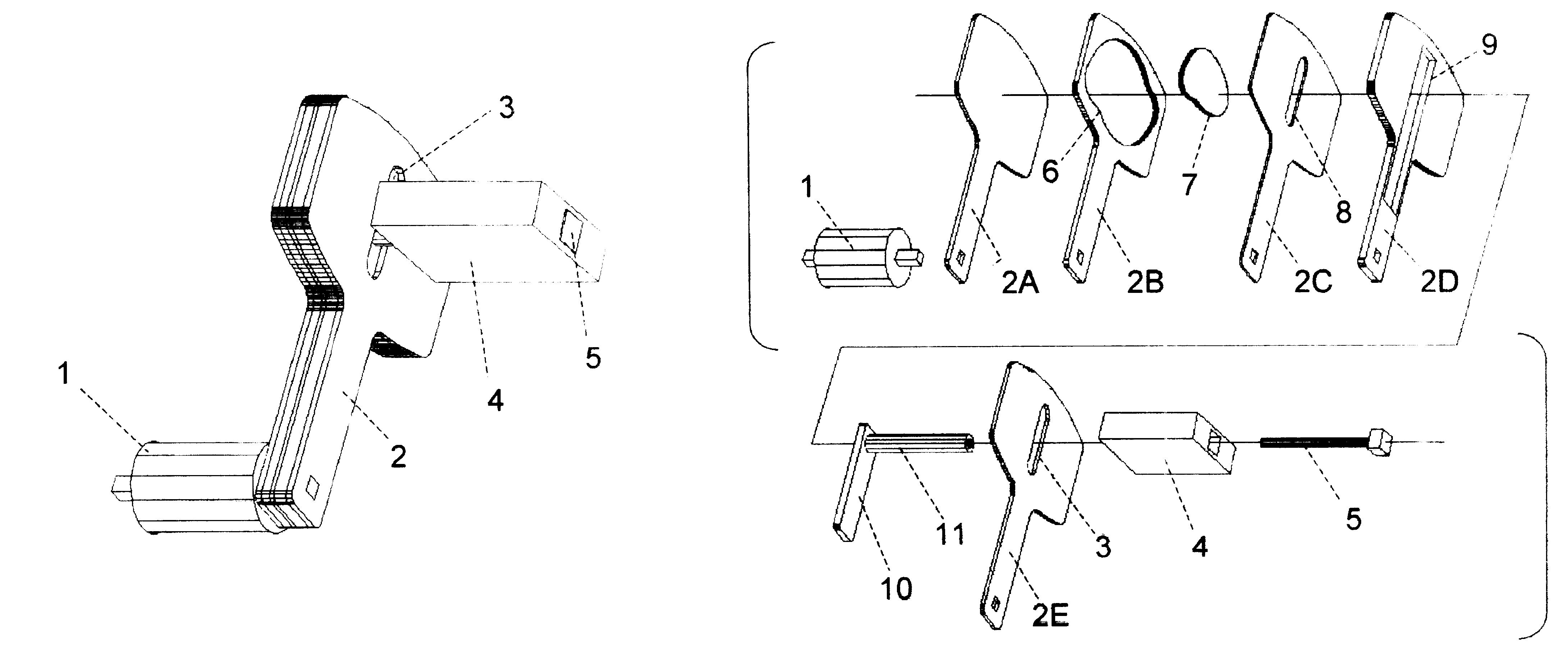
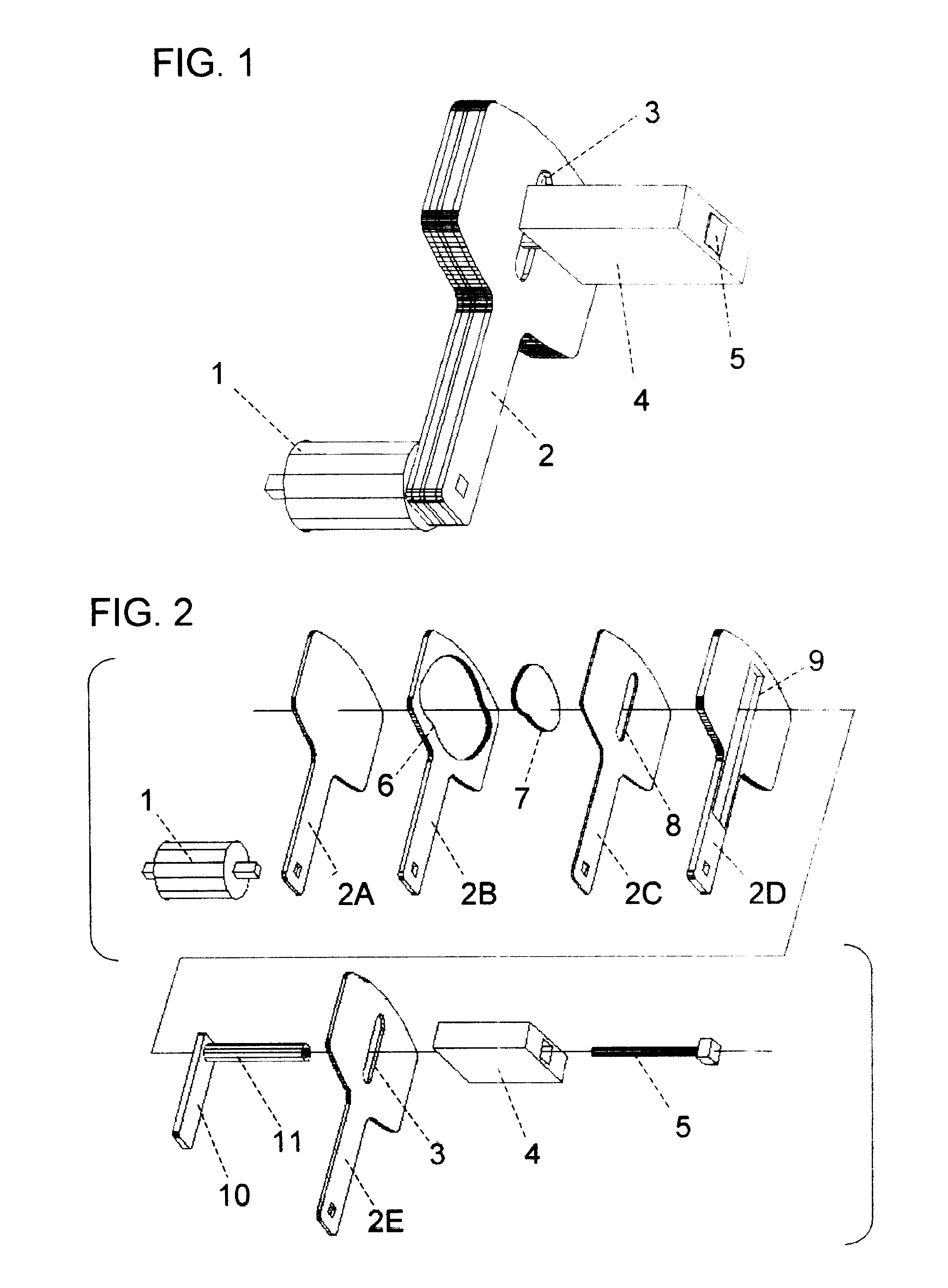
[0027]The crank and pedal assembly has a self-extending and retracting crank arm. It comprises (i) a crank arm that has a cavity for a rotating plate, a track for a bar to move back and forth along the length of the arm, and slits along imaginary lines from the crank axis to the pedal end of the crank arm; (ii) a bar that moves on a track in the crank arm and has a pedal spindle fixed to it at one end; and (iii) a subassembly in which a plate and a pedal are fixed to the opposite ends of a plate shaft. The pedal spindle and the plate shaft pass through the slits in the crank arm to reach the bar and the plate, respectively. They have co-located axes and the plate shaft is partially inside a cylindrical hole along the axis of the pedal spindle. Their movements are restricted by the slits to movements closer to or farther away from the crank axis. During cycling, the pedal rotates the plate inside the plate cavity and the perimeter surface of the cavity operatively cooperates with the...

second embodiment

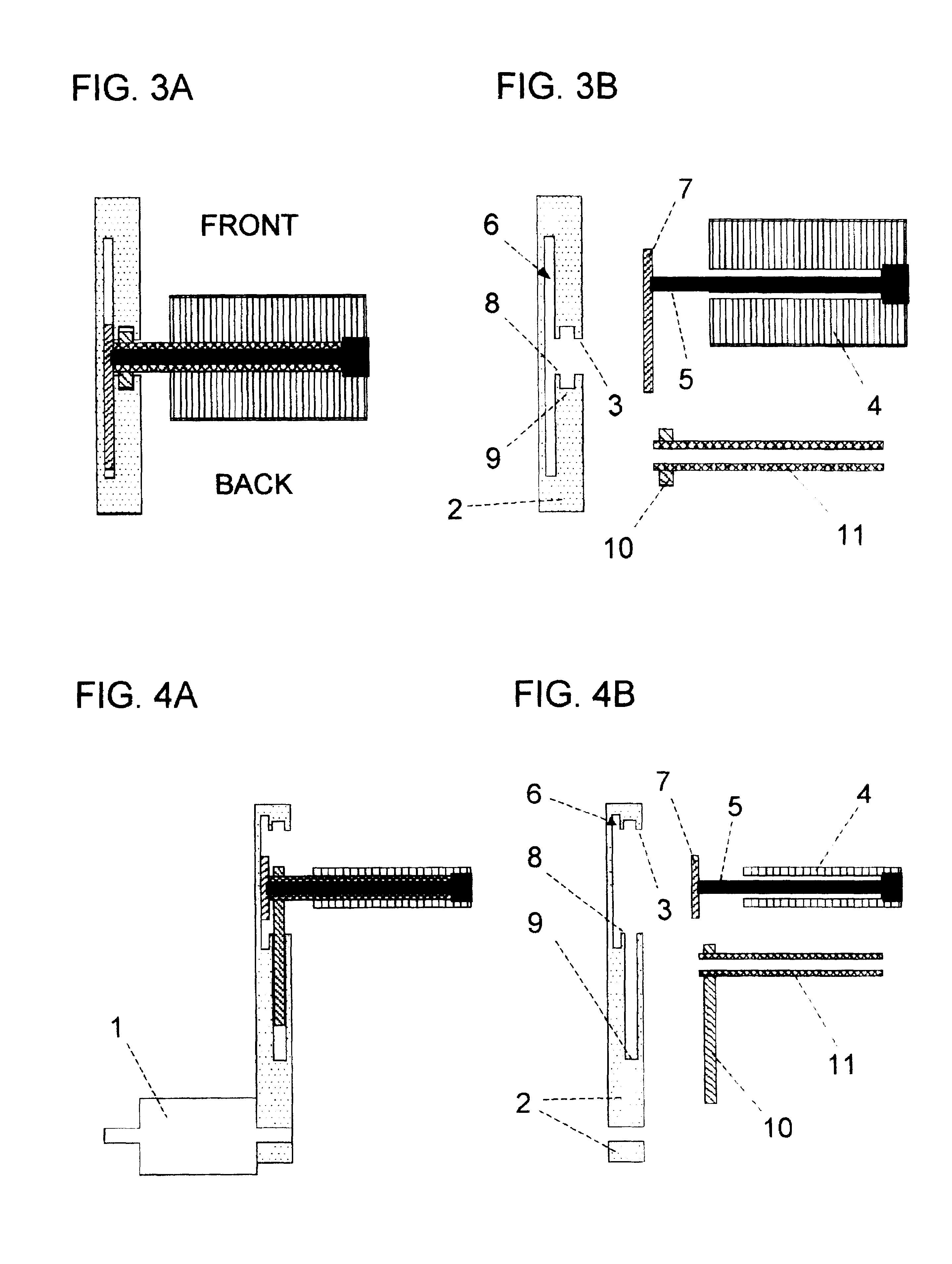
[0038]The second embodiment is obtained from the first by exchanging the positions of the bar 10 and slice 2D with those of the plate 7 and slice 2B, respectively. FIG. 7 shows an exploded view of the new crank and pedal assembly after the exchange. The crank arm is at the one o'clock direction. FIG. 8A shows a sectional view of the new assembly in the horizontal plane through the plate shaft 5 and FIG. 8B shows the three one-piece components of the assembly in FIG. 8A. The pedal spindle 11 in this embodiment is a solid rod and the plate shaft 5 has a cylindrical hole for the spindle 11 to pass through.

third embodiment

[0039]The third embodiment is obtained from the first by deleting the plate and the plate cavity, i.e., deleting the plate 7 and slice 2B, from the design. Its effective arm lengths in the 12–3 o'clock and 6–12 o'clock arm directions depend on the foot motion of the cyclist.


PUM


Abstract

This invention is a bicycle crank and pedal assembly with a self-extending and retracting crank arm. The assembly only has three one-piece components that move relative to each other, if the bearings used in friction reduction are ignored. It is simple in design, compact in size and very effective in delivering the benefits of a self-extending and retracting crank arm. In particular, the assembly has (a) the maximum arm length for over 90 degrees of arm directions in the power down stroke and (b) the minimum arm length for close to 90 degrees of arm directions in the return up stroke.

Description

FIELD OF THE INVENTION[0001]This invention relates to a bicycle crank and pedal assembly with a self-extending and retracting crank arm.BACKGROUND OF THE INVENTION[0002]This invention relates to a bicycle crank and pedal assembly and, more particularly, to an assembly with a self-extending and retracting crank arm.[0003]The length of the crank arm in a bicycle is a compromise between performance and comfort. A longer arm allows a cyclist to travel at the same speed with a lower pedal effort or a slower pedal turning rate, or both. However, the longer arm increases the size of the pedal track round the crank axle and causes discomfort to the leg. One method to get the benefit of a longer arm without getting the discomfort is to extend the arm beyond the compromised length during the pedal power down stroke and retract it below this length in the return upstroke.[0004]Using a longer crank arm is not equivalent to using a lower gear ratio in cycling. A lower gear ratio allows the cycli...

Claims


Application Information

Patent Timeline
Patent Type & Authority Patents(United States)
IPC IPC(8): B62M3/00G05G1/48B62M3/04
CPCB62M3/04Y10T74/2167
Inventor HUNG, ERIC KAM-LING
Owner HUNGS CRANKARM
Why Eureka
Try Eureka