Backlight unit, liquid crystal display device using the same, and method of fabricating the same

a liquid crystal display and backlight technology, applied in lighting device details, lighting and heating apparatus, instruments, etc., can solve the problems of consuming large amounts of power, complicated and time-consuming process of changing or repairing ccfls b>30, and achieve efficient repair and maintenance. , the effect of minimizing the contamination of the liquid crystal display panel

Active Publication Date: 2006-08-22
LG DISPLAY CO LTD
View PDF4 Cites 40 Cited by
  • Summary
  • Abstract
  • Description
  • Claims
  • Application Information

AI Technical Summary

Benefits of technology

[0012]An object of the present invention is to provide a liquid crystal display device capable of being efficiently repaired.
[0013]Another object of the present invention is to provide a method of fabricating a liquid crystal display device capable of being efficiently repaired.
[0014]Another object of the present invention is to provide a liquid crystal display device capable minimizing contamination of the liquid crystal display panel during repair.
[0015]Another object of the present invention is to provide a method of fabricating a liquid crystal display device capable minimizing contamination of the liquid crystal display panel during repair.

Problems solved by technology

However, since the LCD panel is a non-emissive-type display device, an additional light source is required.
In general, the CCFLs 30 remain ON for an extended period of time and consume relatively large amounts of power.
Since the disassembled elements must be re-assembled after changing or repairing any of the CCFLs 30, a process of changing or repairing the CCFLs 30 is complicated and time consuming.
Furthermore, since the LCD panel 70 is exposed during the process of changing or repairing the CCFLs 30, the LCD panel 70 may become contaminated and degrade image display quality.
Thus, production costs increase and efficiency of materials decreases.

Method used


Image

  • Backlight unit, liquid crystal display device using the same, and method of fabricating the same
  • Backlight unit, liquid crystal display device using the same, and method of fabricating the same
  • Backlight unit, liquid crystal display device using the same, and method of fabricating the same

Examples


Embodiment Construction

[0028]Reference will now be made in detail to the preferred embodiments of the present invention, examples of which are illustrated in the accompanying drawings.

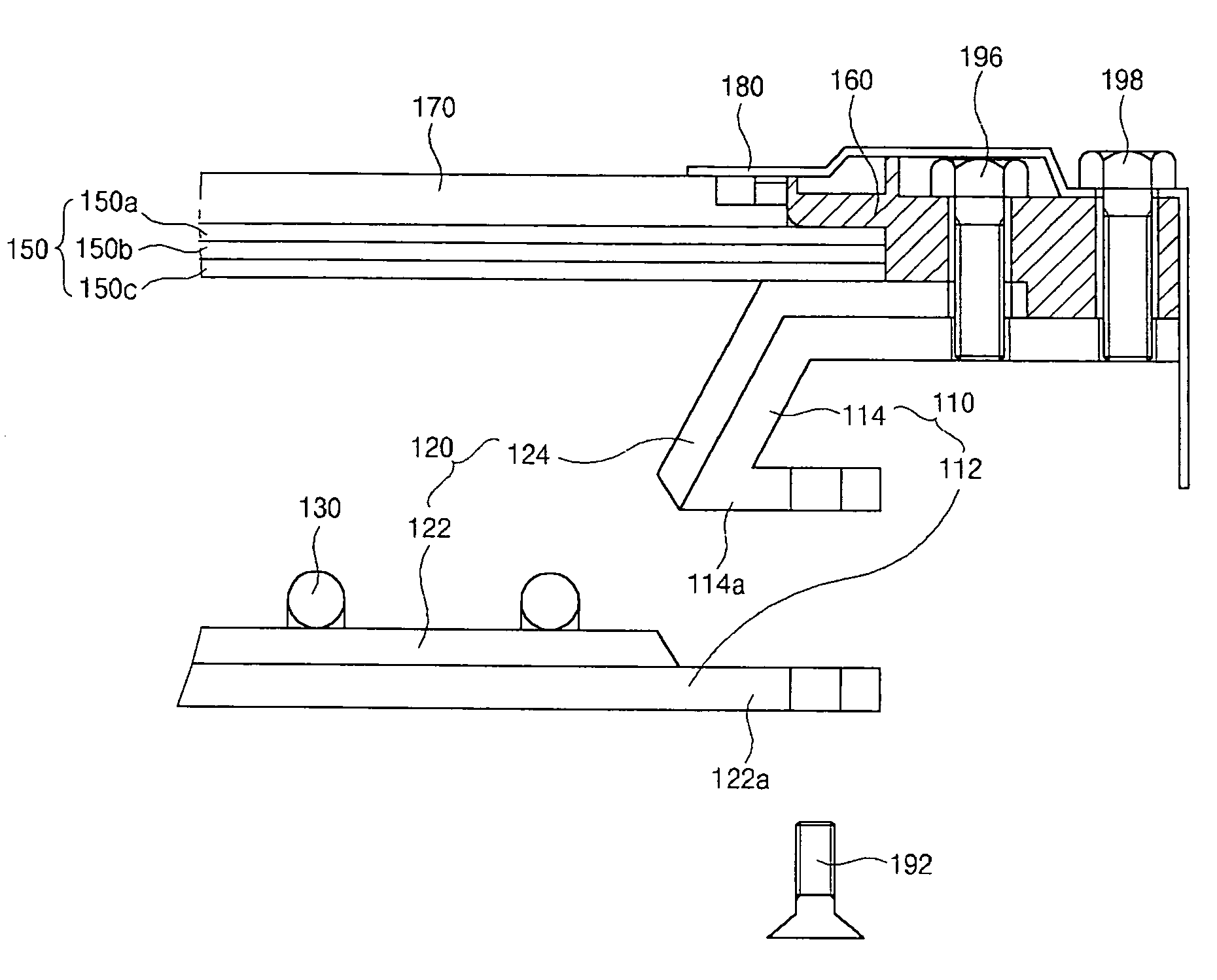
[0029]FIG. 3 is an assembly view of an exemplary liquid crystal display module according to the present invention. In FIG. 3, an LCD module may include an LCD panel 170 and a backlight unit 105, such as a direct-type backlight unit. The backlight unit 105 may include a bottom cover 110, a reflector 120, a plurality of CCFLs 130, a pair of side supporters 140, an optical sheet 150, and a guide panel 160, wherein the bottom cover 110 may be formed of one of metal and-synthetic resin material. The reflector 120 may be formed of metal material having one of a white and silver color, and may be combined with the bottom cover 110. The plurality of CCFLs 130 may be disposed parallel to each other on the reflector 120, wherein the pair of side supporters 140 may cross two ends of each of the CCFLs 130 to fix the plurality of CCFLs 1...


PUM

PropertyMeasurementUnit
weightaaaaaaaaaa
dielectric constantaaaaaaaaaa
refractive indexaaaaaaaaaa

Abstract

A backlight unit for a liquid crystal display device includes a bottom cover having a first plane portion and a first side portion combined by a first coupling system, a reflector over the bottom cover and having a second plane portion and a second side portion corresponding to the first plane portion and the first side portion, respectively, at least one cold cathode fluorescent lamp over the second plane portion, an optical sheet over the at least one cold cathode fluorescent lamp, and a guide panel overlapping a rim portion of the optical sheet, wherein the guide panel and the bottom cover are combined using a second coupling system.

Description

[0001]The present invention claims the benefit of Korean Patent Application No. 2003-9691, filed in Korea on Feb. 17, 2003, which is hereby incorporated by reference.BACKGROUND OF THE INVENTION[0002]1. Field of the Invention[0003]The present invention relates to a display device and a method of fabricating a display device, and more particularly, to a backlight unit, a liquid crystal display device using a backlight unit, and a method of fabricating a liquid crystal display device.[0004]2. Discussion of the Related Art[0005]As the information age progresses, flat panel display (FPD) devices having light weight, thin profile, and low power consumption characteristics are being developed and commonly used as a substitute for cathode ray tube (CRT) devices. Generally, display devices may be classified according to their ability for self-emission, and may include emissive display devices and non-emissive display devices. The emissive display devices display images by taking advantage of...

Claims


Application Information

Patent Timeline
Patent Type & Authority Patents(United States)
IPC IPC(8): G02F1/1333F21V7/04G02F1/13G02F1/13357
CPCG02F1/133604G02F1/133608G02F1/133308G02F2201/46G02F2001/133314G02F1/133314G02F1/1335
Inventor JANG, MYONG-GI
Owner LG DISPLAY CO LTD
Why Eureka
Try Eureka