Positive lock piece and electrical connector assembly equipped with same

a technology of positive lock and electrical connector, which is applied in the direction of electrical apparatus, substation/switching arrangement details, coupling device connections, etc., can solve the problems of lack of certain desireable attributes, and lack of positive lock in usb connection, etc., to achieve easy and inexpensive, easily and conveniently attached

Active Publication Date: 2006-08-22
APTIV TECH LTD
View PDF6 Cites 39 Cited by
  • Summary
  • Abstract
  • Description
  • Claims
  • Application Information

AI Technical Summary

Benefits of technology

[0005]This invention provides an easy and inexpensive positive lock piece for an electrical connector assembly that requires little modification to a standard electrical USB connector when used in a typical USB connection system.
[0006]The positive lock piece preferably comprises a single, loose piece, molded plastic part that is easily and conveniently attached to an electrical connector or an easily modified standard USB connector for shipment and handling. The positive lock piece merely requires inexpensive modifications to the terminal of the standard USB connector which permit the positive lock piece to be mounted and retained on the USB connector. The positive lock piece carried by the USB connector then snap locks onto a face plate to retain the terminals of the connection system in full mated engagement with a USB connector that is behind the face plate.

Problems solved by technology

Since these standard, consumer electronics connection systems are not designed for the automotive environment and usage, they lack certain desireably attributes.
For the standard USB connection, the lack of a positive connector lock is a deficiency.
The lack of a positive lock in a USB connection is a particularly serious deficiency in automotive applications because the USB connectors can not be plugged in reliably in a vehicle assembly plant and can not be reliably expected to remain fully mated in operation due to vehicle vibration and shock.
A complete re-design of the USB connection interface for automotive usage is not feasible due to the expense involved and the desire to maintain the connection as close to the existing standard as possible.

Method used


Image

  • Positive lock piece and electrical connector assembly equipped with same
  • Positive lock piece and electrical connector assembly equipped with same
  • Positive lock piece and electrical connector assembly equipped with same

Examples


Embodiment Construction

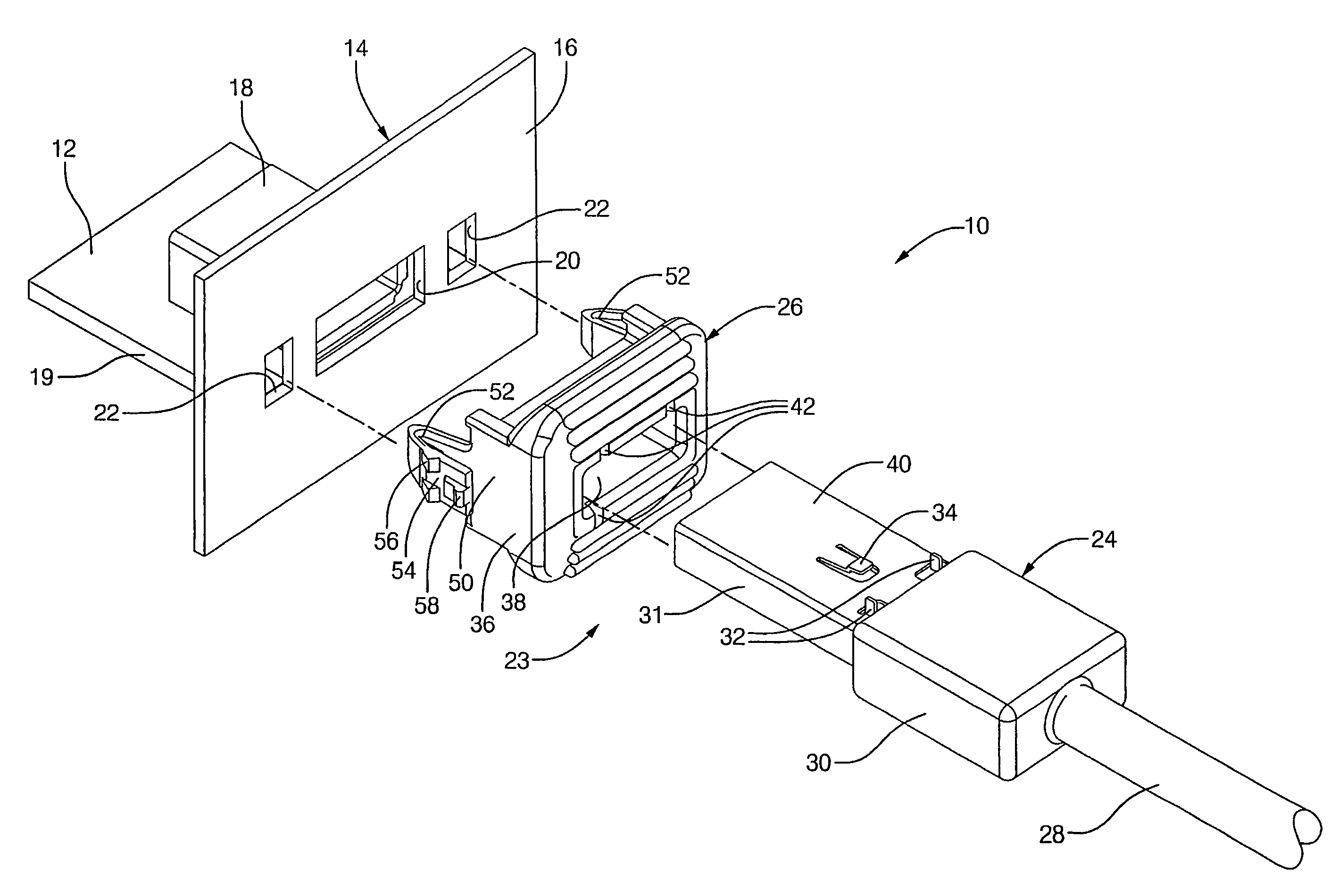
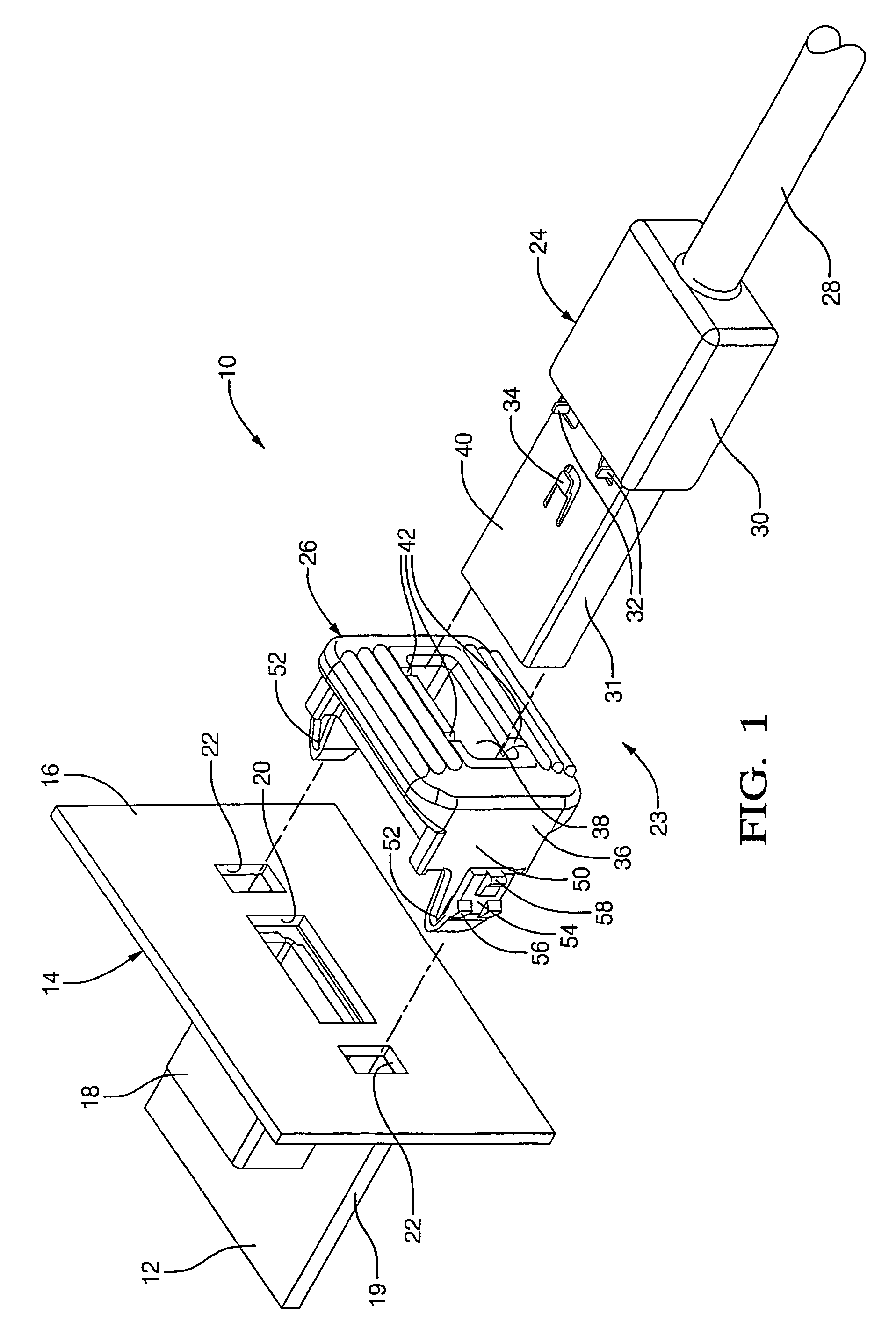
[0011]Referring now to the drawing, FIG. 1 is an exploded perspective view of an electrical connection system having an electrical connector assembly equipped with a positive lock piece of the invention. More particularly, the electrical connection system 10 comprises an electronic component 12 that is disposed in a housing 14 having a face panel 16. Electronic component 12 has a standard USB socket connector 18 disposed behind an opening 20 in face panel 16. The standard USB socket connector 18 is in the form of a header connector that is attached to a printed circuit board 19 or the like of the electronic component 12, which for instance may be a radio in an automotive passenger compartment. Face panel 16 preferably also has attachment openings 22 on either side of access opening 20.

[0012]Electrical connection system 10 further includes an electrical connector assembly 23 comprising a USB plug connector 24 that is equipped with a positive lock piece that is shown generally at 26. ...


PUM


Abstract

An electrical connector assembly comprises an electrical USB connector that has a separate lock piece attached to the terminal of the electrical connector. The lock piece has a collar that fits onto the terminal adjacent to the connector body of the electrical connector. The collar has orientation slots that receive tabs of terminal to properly orient the positive lock piece onto the terminal and inner retention shoulders that cooperate with lock fingers of the terminal for locking the positive lock onto the terminal. A flange attached to the collar serves as a finger guard and push surface when the collar is attached to the terminal. The lock piece has lock arms for attaching the collar to a face panel.

Description

FIELD OF THE INVENTION[0001]This invention relates generally to an electrical connector and more particularly to a positive lock piece and an electrical connector assembly equipped with the positive lock piece, particularly an electrical connector assembly that includes a USB connector.BACKGROUND OF THE INVENTION[0002]With the proliferation of consumer electronics hardware in vehicle applications, the need to incorporate existing non-automotive connection systems, such as USB connectors, is required. Since these standard, consumer electronics connection systems are not designed for the automotive environment and usage, they lack certain desireably attributes.[0003]For the standard USB connection, the lack of a positive connector lock is a deficiency. See for instance U.S. Pat. No. 6,491,541 granted to Jun Wakino Dec. 10, 2002 for a USB cable fixture for preventing a USB connector from being unplugged. The lack of a positive lock in a USB connection is a particularly serious deficien...

Claims


Application Information

Patent Timeline
Patent Type & Authority Patents(United States)
IPC IPC(8): H01R13/60H01R13/66
CPCH01R13/6273H01R13/745H01R13/6395H01R31/06
Inventor DAGGETT, BARRY M.BLASKO, RAYMOND J.
Owner APTIV TECH LTD
Why Eureka
Try Eureka