Female terminal fitting and method of assembling such terminal fitting

a terminal fitting and female technology, applied in the direction of coupling contact members, coupling device connections, electrical devices, etc., can solve the problems of insufficient contact pressure with the male terminal fitting, the effort to miniaturize the female terminal fitting, etc., and achieve the effect of high contact pressure and sufficient width

Inactive Publication Date: 2006-08-22
SUMITOMO WIRING SYST LTD
View PDF7 Cites 49 Cited by
  • Summary
  • Abstract
  • Description
  • Claims
  • Application Information

AI Technical Summary

Benefits of technology

[0007]The invention relates to a female terminal fitting with at least one resilient contact that has a contact surface for contacting a mating male terminal fitting. The female terminal fitting also has at least one support that can support a surface of the resilient contact opposite from the contact surface. The support extends at an angle to the longitudinal direction of the female terminal fitting, and preferably at a substantially right angle. The extension of the support at an angle to the longitudinal direction of the female terminal fitting ensures a sufficient width even for a small female terminal fitting. Thus, the strength of the support and the resilient force of the resilient contact are sufficiently high to attain a high contact pressure.
[0012]The cover may have an insertion hole into which the mounting member is insertable. The cover also may have at least one fitting recess into which the leading end of the support is fittable. The engagement of the leading end of the support in the fitting recess of the cover enhances the strength of the support and thus enhances the contact pressure.
[0013]The female terminal fitting preferably has two opposed resilient contacts that substantially face each other. Additionally, the mounting member preferably has two supports extend in substantially the same direction from the opposite ends of the base portion. The mounting member is mounted so that the supports hold the resilient contacts therebetween. Thus, the resilient contacts can be supported satisfactorily by the supports.

Problems solved by technology

However, problems arise in efforts to miniaturize the female terminal fitting 5.
As a result, the resilient contact pieces 2 are not supported sufficiently, and a contact pressure with the mating male terminal fitting may be insufficient.

Method used


Image

  • Female terminal fitting and method of assembling such terminal fitting
  • Female terminal fitting and method of assembling such terminal fitting
  • Female terminal fitting and method of assembling such terminal fitting

Examples


first embodiment

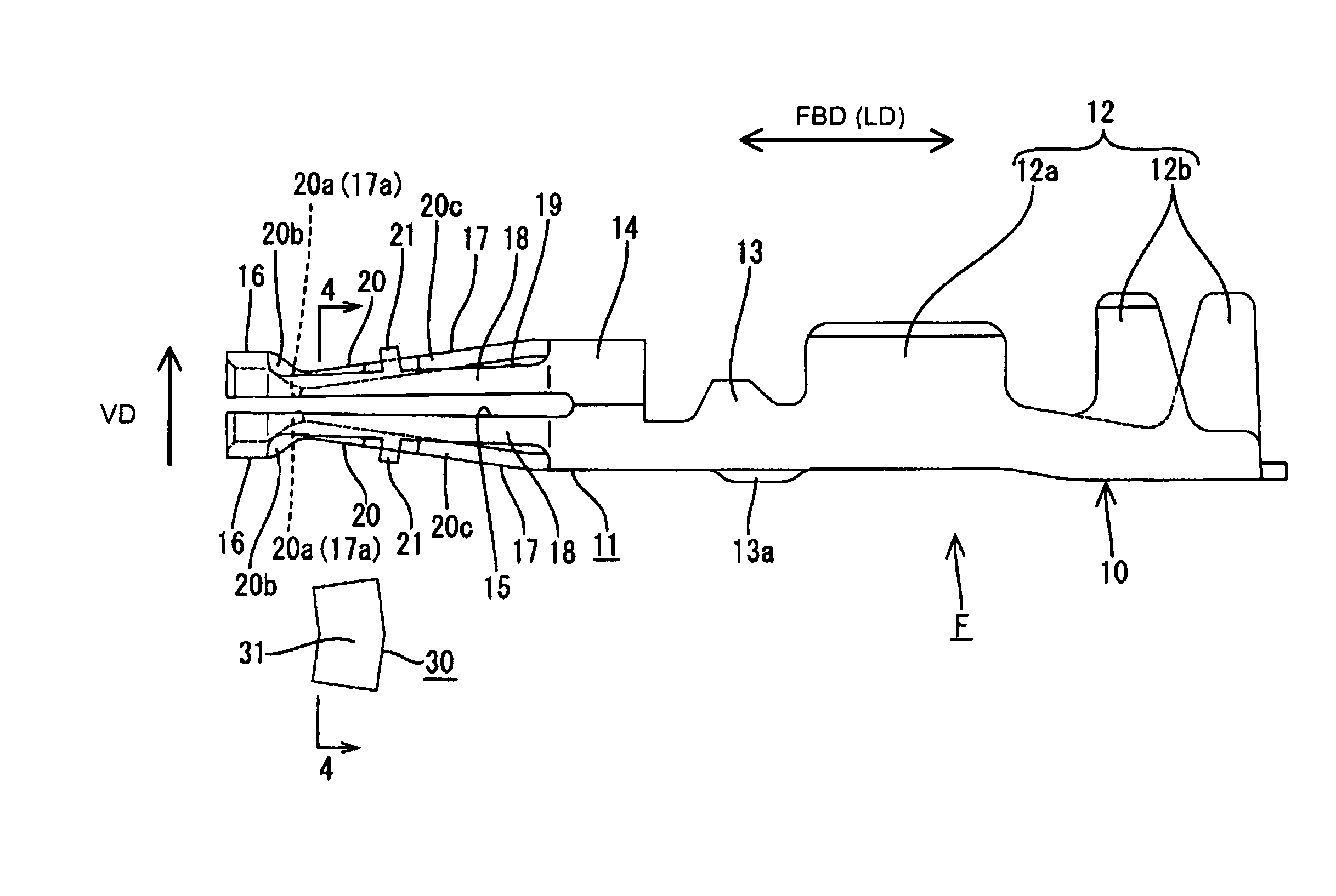
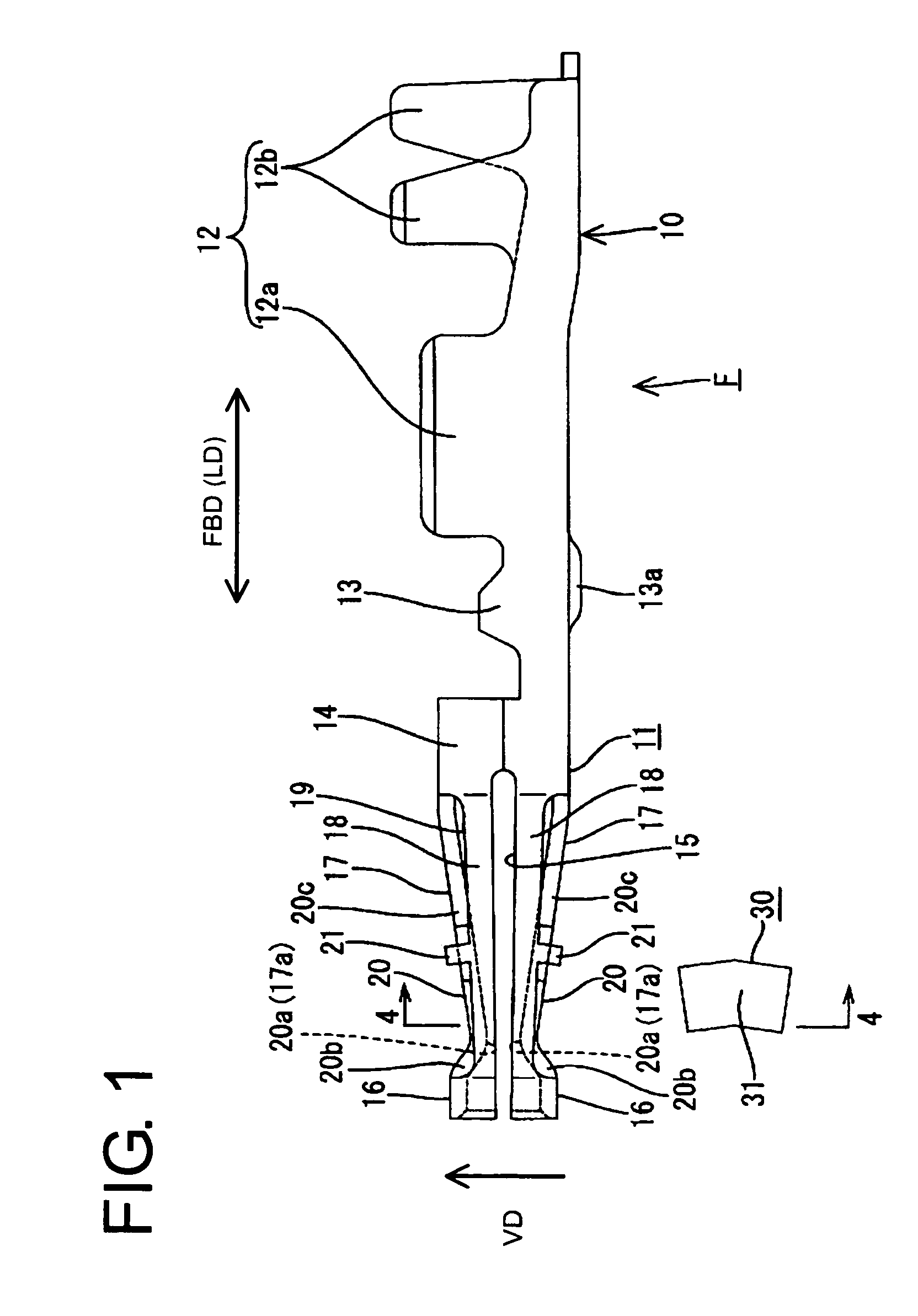
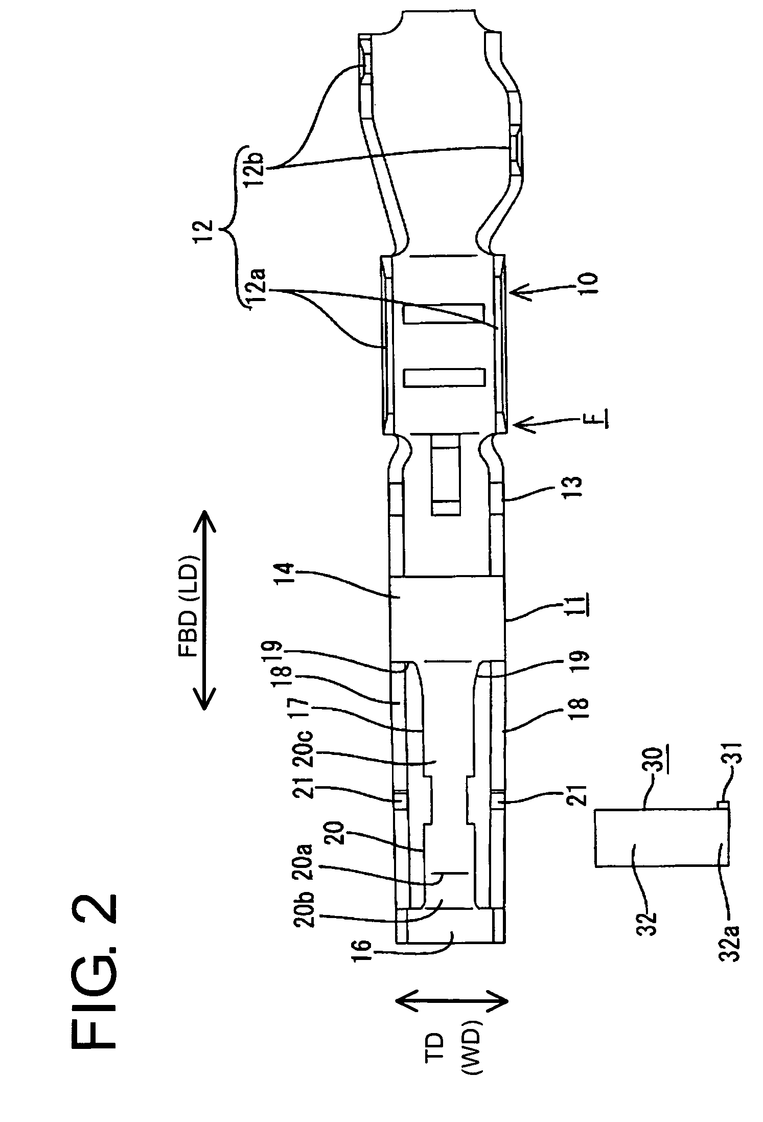
[0036]A female terminal fitting according to the invention is identified by the letter F in FIGS. 1 to 8. In the following description, an end of the female terminal fitting F that mates with a mating male terminal fitting M (left side in FIGS. 1 and 2) is referred to as the front and the opposite end is referred to as the back. Reference also is made to the drawings (except FIGS. 2 and 7) concerning vertical direction VD.

[0037]The female terminal fitting F has a terminal main body 10 that is formed from a conductive plate (e.g. a copper alloy) that has been stamped or cut out into a specified two-dimensional shape and then bent, folded and / or embossed into a desired three-dimensional shape. As shown in FIGS. 1 and 2, the terminal main body 10 is comprised of an inserting portion 11, a barrel 12 and a coupling 13 that couples the inserting portion 11 and the barrel 12. The barrel 12 has two front crimping pieces 12a that are to be crimped, folded or bent into connection with a core ...

second embodiment

[0050]The female terminal fitting F of the second embodiment has a cover 40 mounted on the terminal main body 10A. The cover 40 has a substantially box shape and is hollow along forward and backward directions FBD, as shown in FIGS. 9 to 11. The cover 40 is formed by bending, folding and / or embossing a plate (e.g. of stainless steel) that has been stamped or cut out into a specified shape. The inserting portion 11 of the terminal main body 10A is insertable into the cover 40 from behind and is substantially entirely covered by the surrounding walls of the cover 40. A male terminal fitting M is insertable from the front through a front opening of the cover 40. The rear end of the cover 40 has a channel-shaped extension for covering the coupling 13 of the terminal main body 10A. Two crimping pieces 41 project from this extension and are crimped, bent or folded into connection with the opposite side walls of the coupling 13 to secure the cover 40 to the terminal main body 10A. The fron...


PUM


Abstract

A female terminal fitting (F) has a terminal main body (10) with an inserting portion (11) that has two opposed resilient contacts (17) for receiving a male terminal fitting (M). A mounting member (30) is mountable sideways onto the inserting portion (11). The mounting member (30) has a base (31) and two supports (32) that extend in a widthwise direction from opposite ends of the base (31). The supports (32) are located to support the outer surfaces of the resilient contacts (17) opposite from contact surfaces (17a) with the male terminal fitting (M).

Description

BACKGROUND OF THE INVENTION[0001]1. Field of the Invention[0002]The invention relates to a female terminal fitting with resilient contact pieces.[0003]2. Description of the Related Art[0004]U.S. Pat. No. 5,246,390 and FIG. 17 herein disclose a female terminal fitting. As shown in FIG. 17, the female terminal fitting 5 has a terminal main body 1 with two resilient contact pieces 2. The resilient contact pieces 2 have opposed facing contact surfaces that can be brought into contact with a mating male terminal fitting. A rectangular tubular cover 3 is fitted on the terminal main body 1. The cover 3 is cut and bent to form two resilient supports 4 that cantilever along the longitudinal direction of the female terminal fitting 5. Each resilient support 4 has a free end supported in contact with the outer surface of the corresponding resilient contact piece 2 opposite from the contact surface thereof. Thus, the supports 4 enhance the resilient force of the contact pieces 2 and increase a ...

Claims


Application Information

Patent Timeline
Patent Type & Authority Patents(United States)
IPC IPC(8): H01R4/48H01R13/11H01R13/18
CPCH01R13/18
Inventor KURIMOTO, NAOYA
Owner SUMITOMO WIRING SYST LTD
Why Eureka
Try Eureka