High-resolution 3D ultrasonic transmission imaging

a transmission imaging and high-resolution technology, applied in the field of high-resolution 3d ultrasonic transmission imaging, can solve the problems of limited image resolution and long scanning time of objects of interest, and achieve the effects of high signal-to-noise ratio, minimal crosstalk, and high resolution

Inactive Publication Date: 2006-08-22
ALFRED E MANN INST FOR BIOMEDICAL ENG AT THE UNIV OF SOUTHERN CALIFORNIA
View PDF27 Cites 31 Cited by
  • Summary
  • Abstract
  • Description
  • Claims
  • Application Information

AI Technical Summary

Benefits of technology

[0009]The present invention rapidly creates a high resolution 3D image by scanning an object using at least one transmitter and at least one receiver. When there are multiple transmitter and receiver elements, there is minimal crosstalk between signals, and a high signal to noise ratio (SNR) at the receiver.

Problems solved by technology

There are often several limitations in this prior art, such as: (i) the resolution of the image of the object is limited, (ii) the time for scanning an object of interest may be quite long, and (iii) there are errors due to cross talk or multipath effects when multiple transmitter elements are used for simultaneously transmitting signals.
No comparable imaging systems are known for transmission mode where the receiver element can operate on a signal attenuated and diffracted about an object.

Method used


Image

  • High-resolution 3D ultrasonic transmission imaging
  • High-resolution 3D ultrasonic transmission imaging
  • High-resolution 3D ultrasonic transmission imaging

Examples


Embodiment Construction

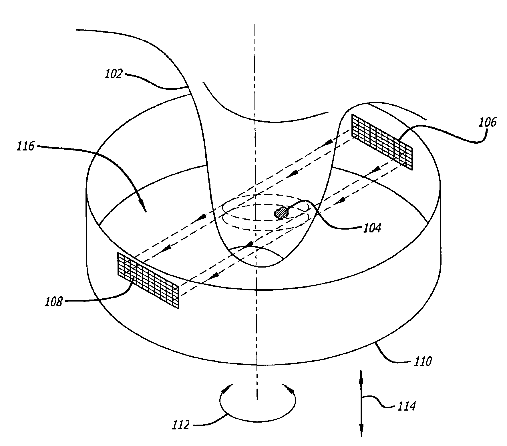
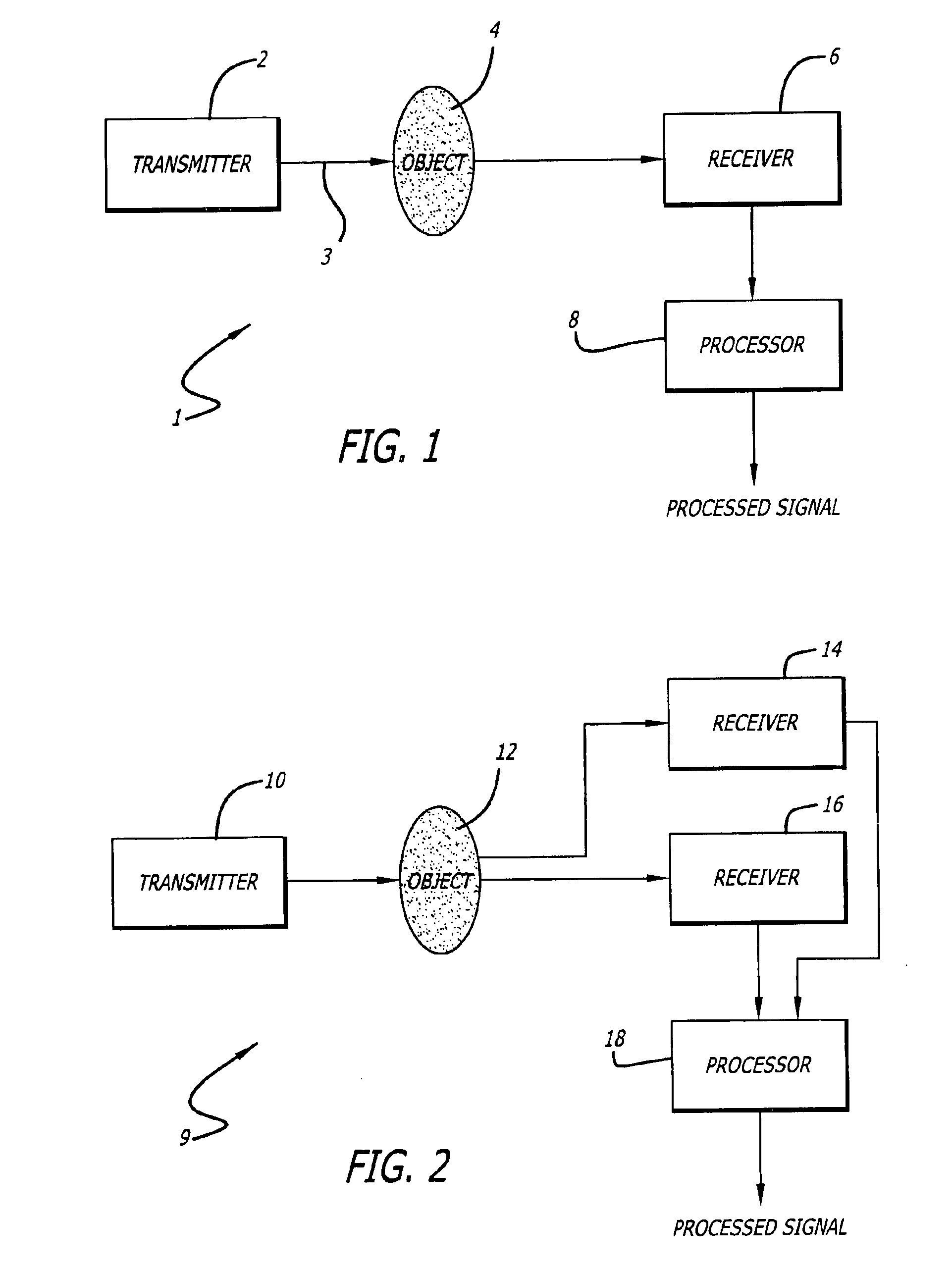
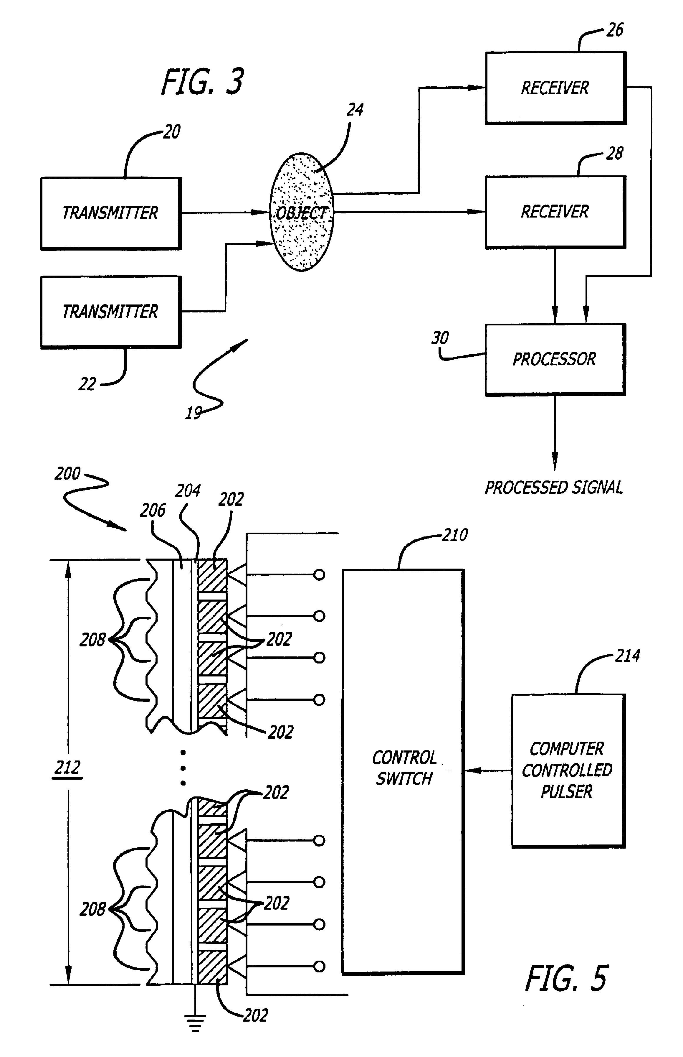
[0028]The general overview of one embodiment of a system 1 incorporating the present invention for creating a high resolution image of an object is shown in FIG. 1. The system includes a transmitter 2 used for transmitting a signal 3, a receiver 4, which may include a piezoelectric transducer, positioned to receive the signal, an area between the transmitter and the receiver for receiving an object 4, and a processor 8 for generating a high resolution output signal. This output signal could be either an analog / digital signal or an image. The object 4 is shown in a position that causes at least portions of the signal 3 to be scattered before it is received by the receiver 6. In one embodiment, the object has at least one dimension less than one millimeter. In one embodiment, the object is a lesion that is to be detected in tomographical applications. The transmitter 2 in one embodiment includes a simple piezoelectric transducer that is excited by a bipolar signal having two levels (e...


PUM


Abstract

A system for providing high resolution imaging of objects having sub-millimeter dimensions comprised of at least one transmitter, at least one receiver, a coupling chamber, and a processor for recording attenuation and time of flight profiles of the transmitted signals. The signals are conditioned in a manner to provide high signal-to-noise ration (SNR) and minimal crosstalk and multipath effects at the receiver.

Description

RELATED APPLICATIONS[0001]The present application claims priority to provisional application Ser. No. 60 / 282,001, filed Apr. 6, 2001, the contents of which are hereby incorporated by reference in their entirety.BACKGROUND OF THE INVENTION[0002]1. Field of the Invention[0003]This invention relates to imaging a three dimensional object using high resolution scanning in tomographical applications.[0004]Specifically, the present invention relates to signal processing systems and methods for creating a high-resolution image of an object using ultrasonic tomography.[0005]2. General Background[0006]Ultrasonic transmission tomography has been used in the past for two dimensional imaging of an object of interest. The signals used for transmission were either pulse or sinusoidal waveforms.[0007]There are often several limitations in this prior art, such as: (i) the resolution of the image of the object is limited, (ii) the time for scanning an object of interest may be quite long, and (iii) t...

Claims


Application Information

Patent Timeline
Patent Type & Authority Patents(United States)
IPC IPC(8): A61B8/02A61B8/00A61B8/06A61B8/08A61B17/22A61B19/00
CPCA61B8/0825A61B8/483A61B8/406A61B2019/205A61B90/17
Inventor MARMARELIS, VASILIS Z.
Owner ALFRED E MANN INST FOR BIOMEDICAL ENG AT THE UNIV OF SOUTHERN CALIFORNIA
Why Eureka
Try Eureka