Method for applying or repairing thermal barrier coatings

a thermal barrier and coating technology, applied in the direction of superimposed coating process, machines/engines, transportation and packaging, etc., can solve the problems of less flexible physical vapor deposition techniques and the way in which they are typically carried ou

Active Publication Date: 2006-08-22
GENERAL ELECTRIC CO
View PDF42 Cites 38 Cited by
  • Summary
  • Abstract
  • Description
  • Claims
  • Application Information

AI Technical Summary

Benefits of technology

[0018]The embodiments of the method of this invention for applying a plasma sprayed thermal barrier coating and for repairing a physical vapor deposition-applied thermal barrier coating provide several benefits. These methods allow a plasma sprayed thermal barrier coating to be applied to an underlying diffusion aluminide coating that overlays the metal substrate of turbine component, such as a combustor deflector plate assembly or combustor nozzle, in a manner that insures adequate adherence of the plasma sprayed thermal barrier coating. These methods also allow the repair of physical vapor deposition-applied thermal barrier coatings without the need to take apart or disassemble the component and without damaging portions of the component, including brazed joints and supporting structures. These methods also allow a relatively less time consuming and uncomplicated way to apply or repair these thermal barrier coating and are relatively inexpensive to carry out. These methods also permit the use of more flexible plasma spray techniques that can be carried out in air and at relatively low temperatures, e.g., typically less than about 800° F. (about 427° C.). By contrast, physical vapor deposition techniques are less flexible and are typically carried out in a vacuum in a relatively small coating chamber and at much higher temperatures, e.g., typically in the range of from about 1750° to about 2000° F. (from about 954° to about 1093° C.).

Problems solved by technology

By contrast, physical vapor deposition techniques are less flexible and are typically carried out in a vacuum in a relatively small coating chamber and at much higher temperatures, e.g., typically in the range of from about 1750° to about 2000° F.

Method used


Image

  • Method for applying or repairing thermal barrier coatings
  • Method for applying or repairing thermal barrier coatings
  • Method for applying or repairing thermal barrier coatings

Examples


Embodiment Construction

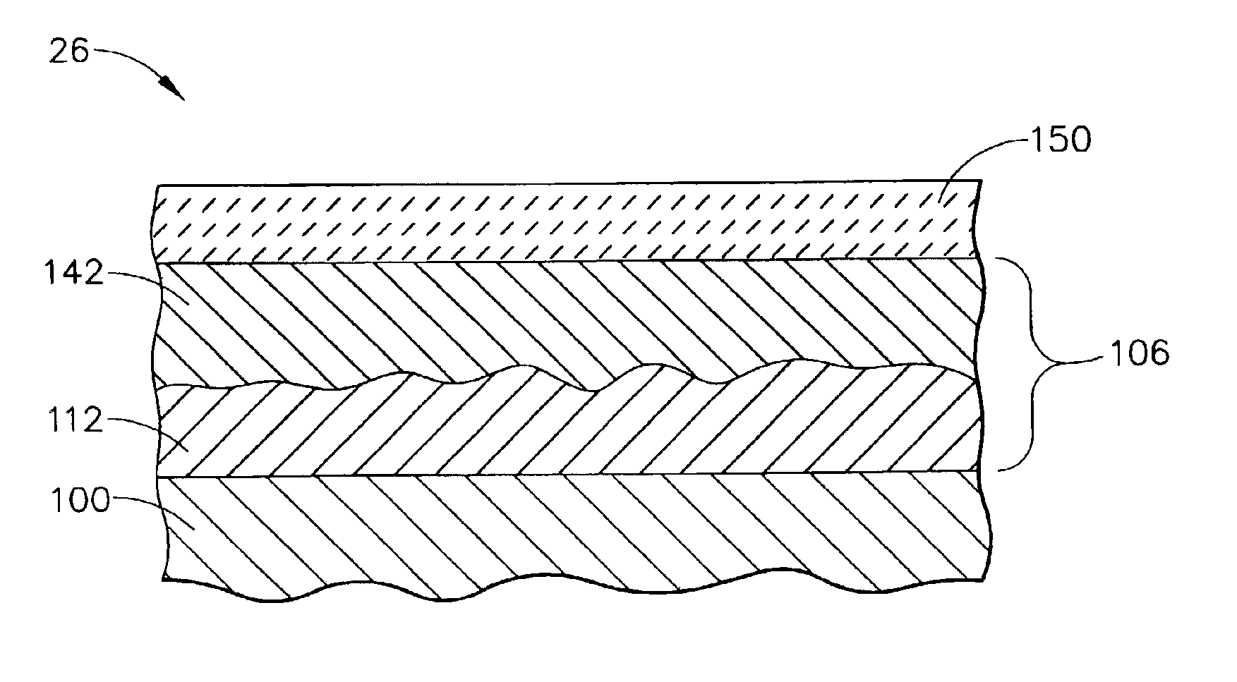
[0025]As used herein, the term “ceramic thermal barrier coating materials” refers to those coating materials that are capable of reducing heat flow to the underlying metal substrate of the article, i.e., forming a thermal barrier and usually having a melting point of at least about 2000° F. (1093° C.), typically at least about 2200° F. (1204° C.), and more typically in the range from about 2200° to about 3500° F. (from about 1204° to about 1927° C.). Suitable ceramic thermal barrier coating materials for use herein include, aluminum oxide (alumina), i.e., those compounds and compositions comprising Al2O3, including unhydrated and hydrated forms, various zirconias, in particular chemically stabilized zirconias (i.e., various metal oxides such as yttrium oxides blended with zirconia), such as yttria-stabilized zirconias, ceria-stabilized zirconias, calcia-stabilized zirconias, scandia-stabilized zirconias, magnesia-stabilized zirconias, india-stabilized zirconias, ytterbia-stabilized ...


PUM

PropertyMeasurementUnit
thicknessaaaaaaaaaa
thicknessaaaaaaaaaa
thicknessaaaaaaaaaa

Abstract

A method applying a thermal barrier coating to a metal substrate, or for repairing a thermal barrier coating previously applied by physical vapor deposition to an underlying aluminide diffusion coating that overlays the metal substrate. The aluminide diffusion coating is treated to make it more receptive to adherence of a plasma spray-applied overlay alloy bond coat layer. An overlay alloy bond coat material is then plasma sprayed on the treated aluminide diffusion coating to form an overlay alloy bond coat layer. A ceramic thermal barrier coating material is plasma sprayed on the overlay alloy bond coat layer to form the thermal barrier coating. In the repair embodiment of this method, the physical vapor deposition-applied thermal barrier coating is initially removed from the underlying aluminide diffusion coating.

Description

BACKGROUND OF THE INVENTION[0001]This invention relates to a method for applying a thermal barrier coating to a metal substrate, or for repairing a previously applied thermal barrier coating on a metal substrate, of an article, in particular turbine engine components such as combustor deflector plates and assemblies, nozzles and the like. This invention further relates to a method for applying a thermal barrier coating, or repairing a previously applied thermal barrier coating, by plasma spray techniques where the underlying metal substrate has an overlaying aluminide diffusion coating.[0002]Higher operating temperatures of gas turbine engines are continuously sought in order to increase their efficiency. However, as operating temperatures increase, the high temperature durability of the components of the engine must correspondingly increase. Significant advances in high temperature capabilities have been achieved through formulation of nickel and cobalt-base superalloys, though suc...

Claims


Application Information

Patent Timeline
Patent Type & Authority Patents(United States)
IPC IPC(8): C23C4/06C23C4/10C23C4/00C23C4/02C23C28/00
CPCC23C4/00C23C4/02C23C28/3215C23C28/3455C23C28/345C23C28/36Y10T428/12618F01D5/005F01D5/288F05D2230/312Y10T29/49318Y10T428/12736
Inventor NAGARAJ, BANGALORE ASWATHALANMAN, EVA ZIELONKASCHORR, DEBORAH ANNETOMLINSON, THOMAS JOHNHEIDORN, RAYMOND WILLIAMKASTRUP, DAVID ALLENYOUNG, CRAIG DOUGLAS
Owner GENERAL ELECTRIC CO
Why Eureka
Try Eureka