Method for encapsulating an electrical component

Inactive Publication Date: 2006-08-22
SNAPTRACK
View PDF7 Cites 15 Cited by
  • Summary
  • Abstract
  • Description
  • Claims
  • Application Information

AI Technical Summary

Benefits of technology

[0005]The object of the present invention is to provide a method for encapsulating an electrical component

Problems solved by technology

It has turned out that the use of a metal foil, as well as the use of a metal-coated plastic film, for direct application on the rear side of a component involves problems, and can result in components whose hermetic sealing is not satisfactory.
In addition, problems occur during the lamination process, because, in particular in th

Method used


Image

  • Method for encapsulating an electrical component
  • Method for encapsulating an electrical component
  • Method for encapsulating an electrical component

Examples


Embodiment Construction

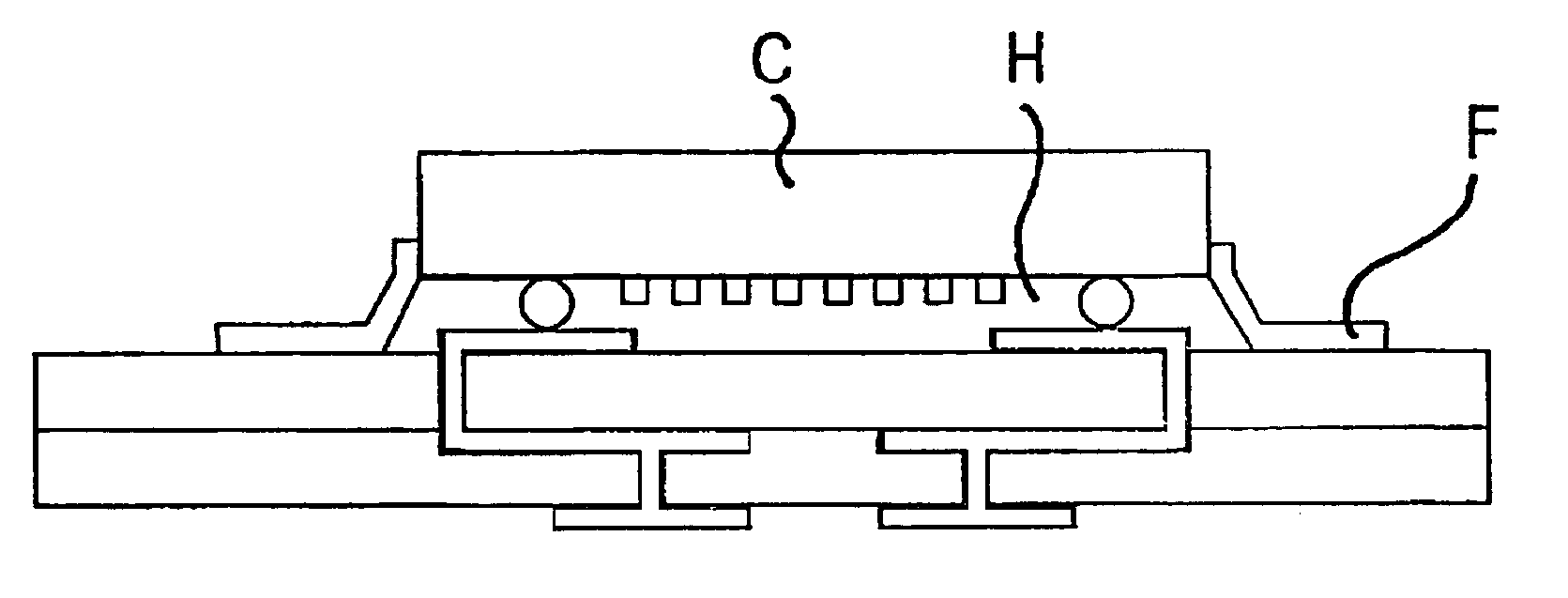
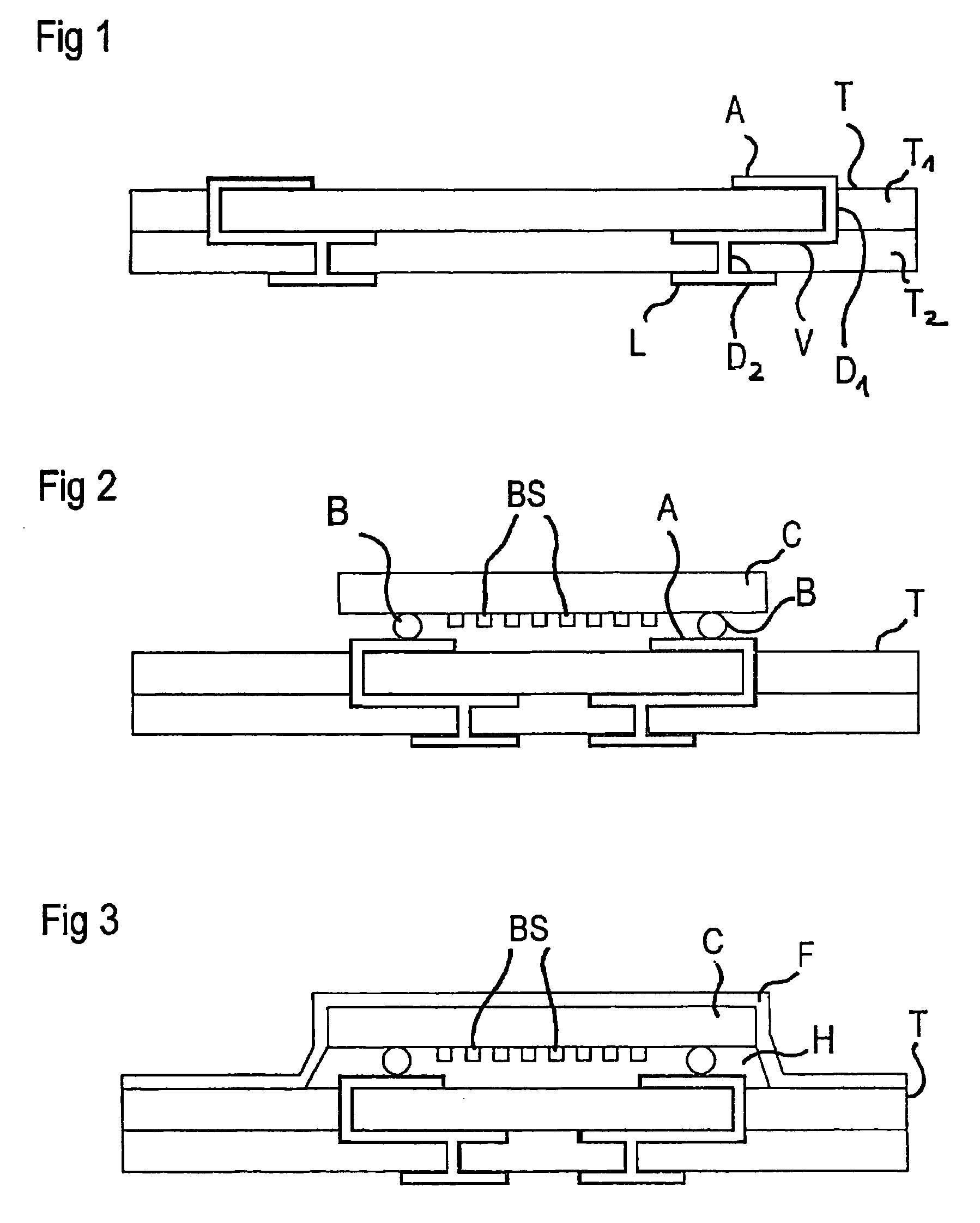
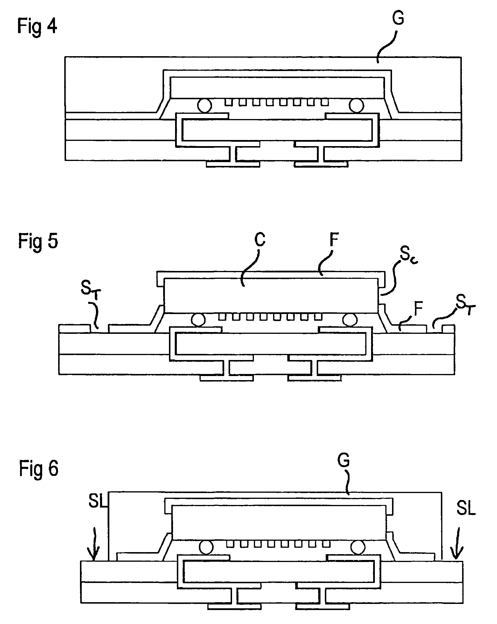
[0017]The underlying idea of the embodiments of the invention that a discussed below, for the encapsulation of electrical components mounted on a carrier using the flip chip technique, is first to laminate these components from the rear with a film, but without using an expensive special film. Rather, in a second step, a plastic / resinous compound is applied, in liquid form, on the carrier with the mounted component and the laminated-on film, in such a way that an inner contact, following at least the outer periphery of the component, is created of the plastic compound to the component, or to the film situated between these, as well as to the carrier, or to the film situated between these.

[0018]In this method, the film is used solely to seal the clearance between the component (chip) and the carrier along the edges of chip, in such a way that the plastic compound applied in liquid form cannot penetrate into the intermediate space, housing the component structures, between the chip an...


PUM


Abstract

An encapsulation method for sensitive composition is provided in which a film, in particular a plastic film, is laminated over the entire surface of an arrangement having a component mounted on a carrier in a flip chip construction. For additional sealing and mechanical stabilization, a plastic compound in liquid form is subsequently applied and hardened so as to surround the chip. Optionally, before the application of the plastic compound, the film can be removed in the area of structuring lines in such a way that the plastic compound can come into contact both with the carrier and with the chip surface.

Description

BACKGROUND OF THE INVENTION[0001]A method for the hermetic encapsulation of a component is known, for example, from International Patent Publication No. WO 99 / 43084. There, components, in particular surface acoustic wave devices, are applied, using the flip chip technique, on a carrier that is provided with solderable terminal surfaces. The component is soldered on the carrier over bumps (solder balls), with a clearance from the carrier element, in such a way that the surface having the component structures is oriented towards the carrier.[0002]For hermetic encapsulation of the components situated on the carrier, the components are finally covered and glued or laminated from the rear with a metal foil or a metal-coated plastic film on the carrier. Here, the film seals tightly between the components and seals tightly with the carrier around them, so that a hermetic encapsulation for the component structures results.[0003]It has also been proposed to further stabilize and further herm...

Claims


Application Information

Patent Timeline
IPC IPC(8): H01L21/44H01L21/60H01L21/56H03H3/08H03H9/05H03H9/10H03H9/25
CPCH03H9/059H03H9/1085H03H9/1078H01L2924/16152H01L2924/15192H01L2224/16225
Inventor STELZL, ALOISKRUGER, HANSFEIERTAG, GREGOR
Owner SNAPTRACK
Why Eureka
Try Eureka