
Methods and apparatuses for selectively limiting undesired radiation

a technology of undesired radiation and methods, applied in the field of optical systems, can solve the problems of difficult and sometimes impossible for the detector to distinguish objects of interest from undesired radiation, and the difficulty of detecting an aircraft flying near the sun, so as to prevent the spillover of attenuation effects

Active Publication Date: 2006-08-22
L3HARRIS CINCINNATI ELECTRONICS CORP
View PDF32 Cites 18 Cited by
  • Summary
  • Abstract
  • Description
  • Claims
  • Application Information

AI Technical Summary

Benefits of technology

"The present invention provides improved methods and apparatuses for selectively limiting the effects of undesired radiation, such as solar radiation, in an optical system. The invention includes various techniques for limiting the amount of infrared radiation that may pass to an infrared sensor, such as using a limiter element or a cold filter. Additionally, the invention includes methods for selectively attenuating low and high frequency radiation using an optical limiter or a photochromic optic. The invention also includes a light detector assembly with multiple fields and optical filters to selectively attenuate light within different wavelength bands. The technical effects of the invention include improved image quality, reduced glare, and improved system performance in imaging applications."

Problems solved by technology

In use, optical systems (e.g., visible or infrared) are often subjected to undesired radiation from the sun or from another light source, for example.
In conventional detectors, such undesired radiation can saturate the detector and make it difficult and sometimes impossible for the detector to distinguish objects of interest from the undesired radiation.
As an example, with conventional infrared imaging systems, it can be difficult to detect an aircraft flying near the sun, as the amount of infrared radiation from the sun is large when compared to the infrared radiation from the aircraft.
The solar radiation can cause blooming in the image, reduce sensitivity in the affected area, and even permanently damage the detector.
Moreover, the intense solar radiation can scatter in the optical components, and such scattering can reduce or eliminate the detector's ability to show the presence of the aircraft.
The sun can also cause similar problems in a system configured to detect light in the visible wavelength band.
Moreover, like solar radiation, radiation from an intense artificial light source (e.g., an incandescent light) aimed in the direction of an optical detector could cause saturation of the optical detector.
However, many such filters typically attenuate the entire image and therefore can simultaneously attenuate radiation from objects of interest, making them more difficult to detect.
However, purely electronic techniques typically cannot accommodate the large flux levels often present (e.g., from the sun) while still providing accurate detection of background and adjacent areas and while quickly recovering from the blooming effect.
In addition, while non-linear absorbers could be utilized, such absorbers usually require extremely high photon flux in the wavelength band of interest (e.g., the infrared band), such as would be emitted from a high power laser, before their attenuating function becomes active.

Method used


Image

  • Methods and apparatuses for selectively limiting undesired radiation
  • Methods and apparatuses for selectively limiting undesired radiation
  • Methods and apparatuses for selectively limiting undesired radiation

Examples


Embodiment Construction

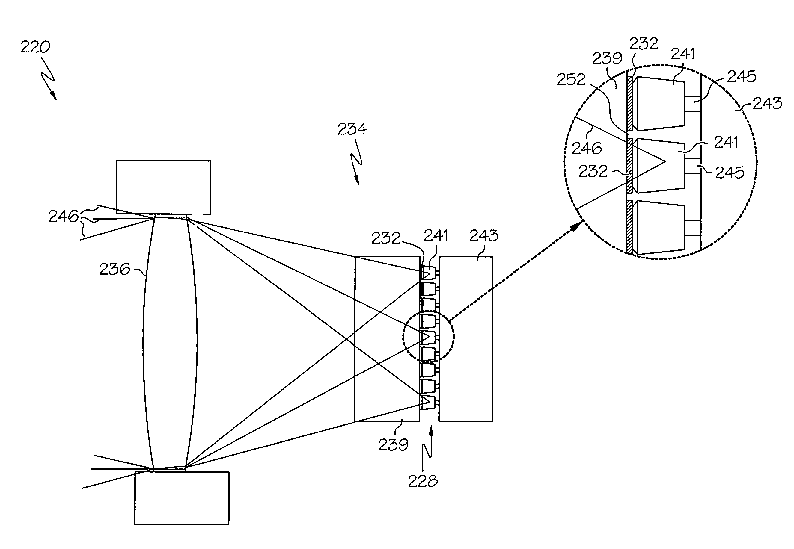
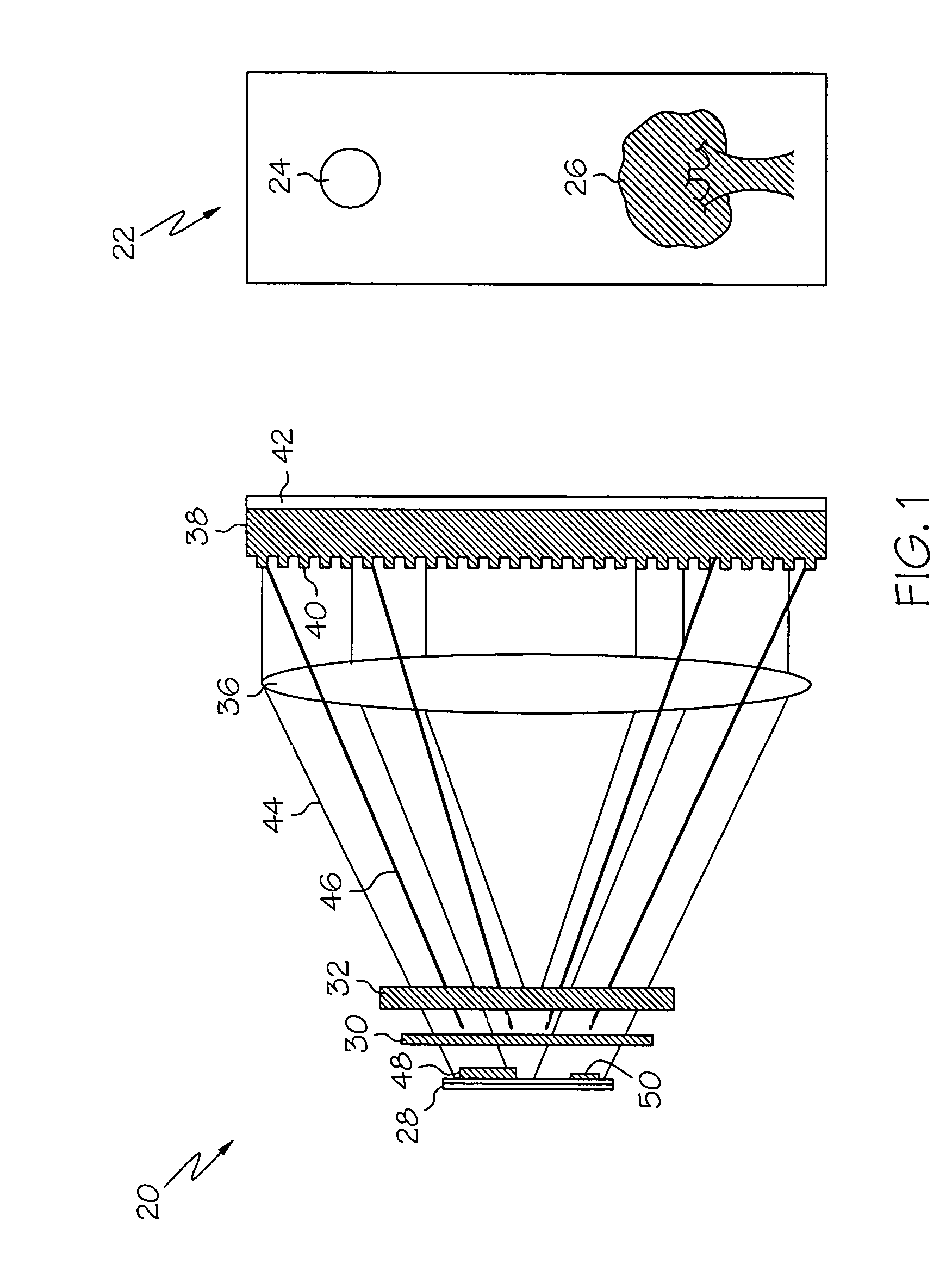
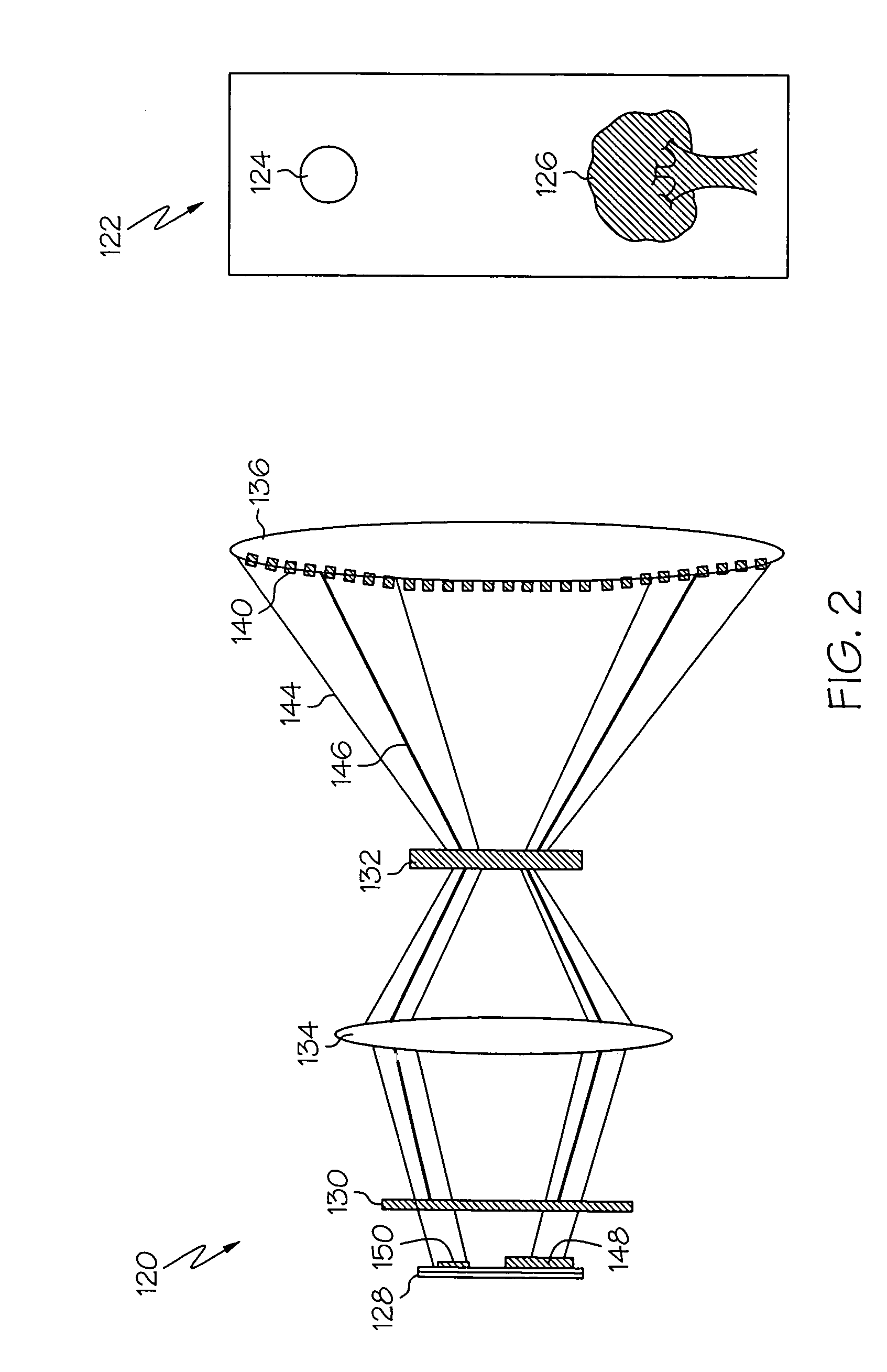
[0021]The present invention and its operation is hereafter described in detail in connection with the views and examples of FIGS. 1–4, wherein like reference numbers indicate the same or corresponding elements throughout the views. FIG. 1 depicts an exemplary detector assembly 20 in accordance with one embodiment of the present invention. Detector assembly 20 might be suitable for association with a digital camera, a digital microscope, digital binoculars, an infrared thermometer, or any other device suitable to detect light emitted or reflected from a scene. In one embodiment, as depicted by FIG. 1, detector assembly 20 can detect light from scene 22, wherein scene 22 can include the sun 24 and a tree 26. Of course, in other embodiments, scene 22 might include any other devices, objects, or living organisms. For example, scene 22 might involve a person, an airplane, a missile, a vehicle, a building, or any other object capable of emitting or reflecting light.

[0022]Detector assembly...


PUM


Abstract

An apparatus for selectively limiting undesired radiation from a scene which, in one embodiment, includes an optic that is operative to attenuate radiation by selectively losing transparency in response to radiation within a first wavelength band from a source. The loss of transparency affects the passage through the optic of radiation within a second wavelength band from that source. The optic can be positioned between a sensor and the scene such that the sensor is configured to receive radiation from the scene through the optic. In one embodiment, an optical limiter includes a plurality of such optics, wherein the optical limiter is configured to facilitate transmission of light corresponding to a scene, and wherein each optic is configured to receive a respective portion of the light corresponding to a respective portion of the scene. A light detector assembly and a method of limiting light energy are also included.

Description

[0001]This application claims the benefit of U.S. Provisional Application Ser. No. 60 / 425,004 filed on Nov. 8, 2002, the entire disclosure of which is hereby incorporated herein by reference.TECHNICAL FIELD[0002]The present invention relates generally to optical systems, and in particular relates to methods and apparatuses for selectively limiting undesired radiation in such systems.BACKGROUND OF THE INVENTION[0003]A variety of optical detection systems have been developed which are sensitive to radiation within various wavelength bands. For example, digital cameras are commercially available to consumers and are configured to detect and record reflections and emissions of light having a wavelength in the visible spectrum band, thereby effectively capturing and recording scenes. As another example, infrared imaging systems are provided to detect radiation in the infrared wavelength band that is emitted from or reflected by objects within a scene. Such infrared imaging systems can vi...

Claims


Application Information

Patent Timeline
Patent Type & Authority Patents(United States)
IPC IPC(8): G01J5/00G01J1/02G01J1/04G01J1/42G01J5/06
CPCG01J1/04G01J1/0407G01J1/0414G01J1/0418G01J5/06G02F1/0126G01J1/42G01J1/0488G02F2203/52G01J2001/0276G02F2203/11
Inventor DEVITT, JOHN W.GREINER, MARK E.VOELKER, JEFFREY J.WADE, DAVID R.
Owner L3HARRIS CINCINNATI ELECTRONICS CORP
Learn More