
Environmentally tuned circuit card assembly and method for manufacturing the same

a circuit card and environment-friendly technology, applied in the direction of sliding card holders, electrical apparatus casings/cabinets/drawers, electrical apparatus construction details, etc., can solve the problems of increasing the failure rate, increasing the size and weight of the circuit card assembly, and damage caused

Inactive Publication Date: 2006-08-22
HONEYWELL INT INC
View PDF28 Cites 90 Cited by
  • Summary
  • Abstract
  • Description
  • Claims
  • Application Information

AI Technical Summary

Benefits of technology

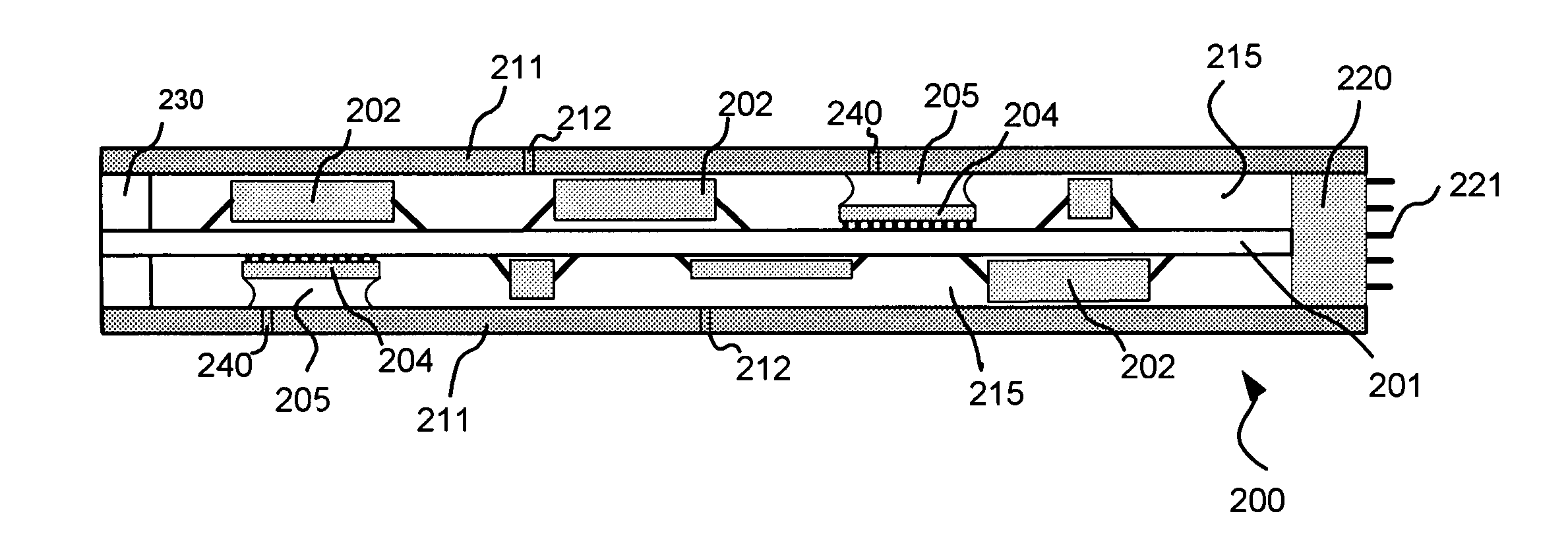
The present invention provides a circuit card assembly with increased rigidity and protection from harsh environments. It uses a composite structure technology to make the assembly more durable and compact. The assembly includes a printed wiring board with electronic components mounted thereon, a shell made of composite material, and a thermal filler and lightweight material to fill the voids between the shell and the printed wiring board and electronic components. The method of manufacturing the assembly involves mounting electronic components on a printed wiring board, placing it in a shell made of composite material, injecting a thermal filler in a region between the shell and at least one electronic component, and then injecting a lightweight filling material to fill any remaining voids in the shell. The technical effects of the invention include increased durability, protection from harsh environments, and the ability to be used in smaller applications.

Problems solved by technology

As more electronic components are included on a circuit card assembly, its failure rate increases when it is subjected to harsh environments, such as harsh dynamic or thermal environments.
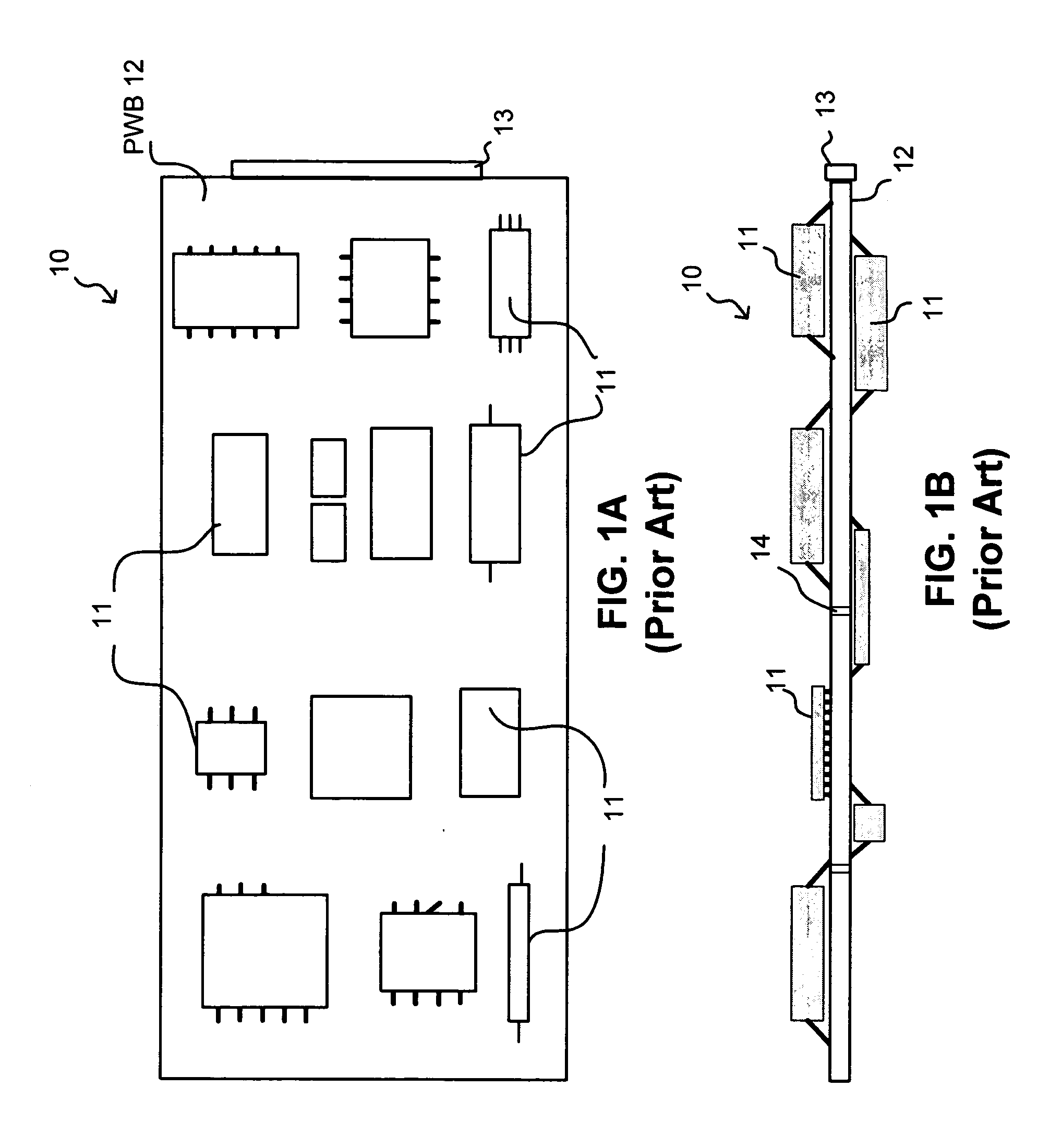
One reason for the higher failure rate is that electronic components 11 are exposed without protection, resulting in damage caused by heat or moisture in the environment.
These stiffening methods (intentional or otherwise), however, significantly increase the size and weight of the circuit card assembly, thereby making such assemblies difficult to work with especially in compact-size electronic devices.

Method used


Image

  • Environmentally tuned circuit card assembly and method for manufacturing the same
  • Environmentally tuned circuit card assembly and method for manufacturing the same
  • Environmentally tuned circuit card assembly and method for manufacturing the same

Examples


Embodiment Construction

[0019]The present invention provides a circuit card assembly with increased rigidity by utilizing lightweight composite structure technology. In accordance with the present invention, the composite structure comprises a thin, stiff outer shell separated by lightweight filler material. The circuit card assembly is disposed inside the shell and surrounded by the filler material.

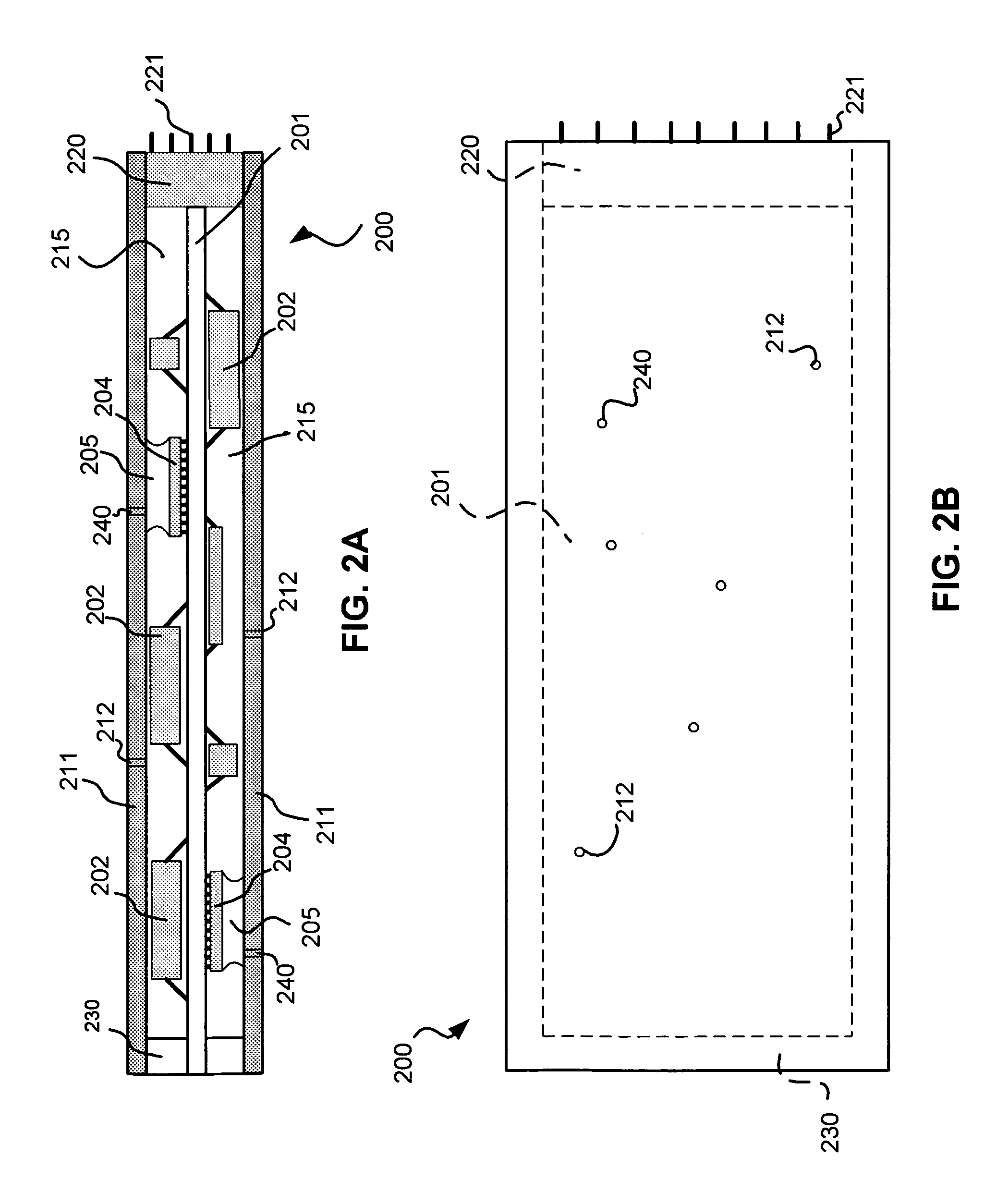
[0020]An exemplary embodiment of the present invention is shown in FIGS. 2A and 2B as lightweight circuit card assembly 200. Although circuit card assembly 200 is shown having a substantially rectangular shape, the present invention is not limited to such a shape or geometry. Other shapes and geometries are possible depending on the particular application.

[0021]Circuit card assembly (CCA) 200 includes a PWB 201 and electronic components 202, 204 attached to both sides of PWB 201. A connector 220 is disposed at an end of CCA 200 and has at least one connecting pin 221 that extends outwardly from CCA 200 for conn...


PUM


Abstract

A circuit card assembly and a method for manufacturing the circuit card assembly are disclosed. The circuit card assembly includes a printed wiring board with electronic components bonded thereto. The printed wiring board and electronic components are placed in an outer shell made of lightweight stiff material. The spaces or voids between the outer shell and the printed wiring board and the electronic components are filled with lightweight filling material and thermal filler material. The outer shell and the filling material provide increased rigidity to the electronic components and the thermal filler material increases heat transfer from a given electronic component to outside the circuit card assembly.

Description

BACKGROUND[0001]1. Field of the Invention[0002]The present invention relates to circuit card assemblies and more particularly, to a structure of a circuit card assembly that can be used in harsh dynamic and thermal environments.[0003]2. Background of the Invention[0004]In an effort to modularize the assembly of electronic devices, electronic components are frequently assembled together on a single circuit card assembly. A circuit card assembly often contains one or more complete circuits for performing selected functions. Circuit card assemblies are typically handled as a single part of a larger circuit or device at assembly time, thereby increasing production speed and simplifying the overall assembly process of the larger circuit or device.[0005]FIGS. 1A and 1B illustrate a prior art circuit card assembly, in which FIG. 1A is a top view of an exemplary circuit card assembly 10 and FIG. 1B is a cross-sectional view thereof. As shown in these Figures, electronic components 11 can be...

Claims


Application Information

Patent Timeline
Patent Type & Authority Patents(United States)
IPC IPC(8): H05K7/20H05K3/28H05K5/06H05K7/14
CPCH05K3/284H05K7/20463H05K7/1461H05K5/064H01L2224/16227H01L2224/32225H01L2924/19041H01L2924/19042H01L2924/19043H01L2924/19106H01L2924/3511
Inventor NICHOLS, RANDOLPH G.
Owner HONEYWELL INT INC
Learn More